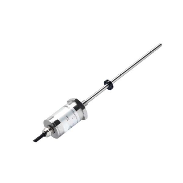
A magnetostrictive position sensor sends a current pulse along a ferromagnetic waveguide. At the location of an external position magnet, the pulse creates a torsional acoustic wave (Wiedemann effect). This wave travels back to the sensing head at a fixed acoustic velocity (~2,830 m/s in nickel alloy). The measured travel time — accurate to nanoseconds — is converted to a position value with ±0.05 mm linearity and 1 μm resolution. No mechanical contact occurs at any point.
The Core Principle: Torsional Acoustic Wave Measurement
The operating principle of a magnetostrictive position sensor is based on the Wiedemann effect — a magneto-mechanical phenomenon in which a ferromagnetic material subjected simultaneously to an axial magnetic field and a circular magnetic field develops a torsional (twisting) stress along its length.
In a magnetostrictive linear position sensor, the sensing element is a thin rod or strip made from a magnetostrictive alloy (typically a nickel-iron or FeNiCo alloy). A brief electrical current pulse is sent along this waveguide. The current pulse generates a circular magnetic field around the rod. Where this field intersects the field of the external position magnet (the float or ring magnet), the Wiedemann effect creates a localized mechanical torsional wave at that precise point.
This torsional wave propagates outward from the generation point in both directions along the waveguide at the acoustic propagation speed of the alloy — approximately 2,830 m/s in nickel-based waveguides. The wave travelling toward the sensing head is detected by a piezoelectric or magnetostrictive pickup at the head. The wave travelling away from the head is absorbed by a damping element at the far end to prevent reflections.
The elapsed time between the emission of the current pulse and the arrival of the torsional wave at the head is measured electronically with nanosecond-class precision. Since the acoustic velocity of the waveguide material is a known, temperature-stable constant, position is calculated as:
Position = Time of Flight × Acoustic Velocity
Where Time of Flight is measured from current pulse emission to torsional wave arrival at the sensing head. Acoustic velocity is constant for the waveguide alloy (~2,830 m/s) and is temperature-compensated in the sensor electronics.
Because the measurement depends only on time-of-flight and a fixed material constant — and because no mechanical contact ever occurs between the position magnet and the waveguide — measurement accuracy does not degrade with use, distance, or stroke length. A 100 mm sensor and a 8,000 mm sensor achieve the same ±0.05 mm linearity.
The Key Components of a Magnetostrictive Position Sensor
Understanding how the sensor works requires knowing what each internal and external component does:
Magnetostrictive Waveguide
The waveguide is the core sensing element — a thin rod or flat strip made from a magnetostrictive ferromagnetic alloy. Current pulses travel along it and torsional waves propagate through it. The waveguide is typically 6–10 mm in diameter for rod-type sensors. Its material composition determines the acoustic velocity and is selected for stability over the operating temperature range.
Position Magnet (Float or Ring Magnet)
The external position magnet slides freely along the outside of the sensor housing without touching the waveguide inside. It is the element that "marks" the measurement position. In liquid level sensors, the magnet is built into a float that rises and falls with liquid level. In displacement sensors, the magnet is a ring that mounts to the moving machine part (e.g., the hydraulic cylinder piston).
Pulse Generator Electronics
The pulse generator sends a precisely timed current pulse down the waveguide at a repetition rate of typically 100–5,000 Hz. Each pulse initiates one measurement cycle. The frequency of pulse generation determines the sensor's update rate — high-speed motion control applications may require 5,000 Hz (5 kHz) update rates, while process monitoring applications typically use 10–100 Hz.
Torsional Wave Detector
At the sensing head, a detection coil or piezoelectric element senses the arriving torsional wave. The wave creates a tiny voltage signal in the coil (inverse Wiedemann effect) or a mechanical stress signal in the piezoelectric element. This signal is amplified and fed to the timing circuit.
Signal Processor and Output Electronics
The signal processor measures the elapsed time between pulse emission and wave detection with nanosecond resolution, applies temperature compensation, computes position, and converts it to the specified output format: 4-20 mA analog, 0-10 V DC, SSI digital, CANopen fieldbus, or RS485 Modbus RTU.
Step-by-Step: What Happens When the Sensor Measures Position
-
Electronics sends current pulse down the waveguide
The pulse generator electronics fires a short, high-frequency current pulse into one end of the magnetostrictive waveguide. This pulse establishes a circumferential (circular) magnetic field along the entire length of the waveguide simultaneously.
-
Torsional wave is generated at the magnet position (Wiedemann effect)
At the exact axial location where the position magnet sits alongside the waveguide, the circular field from the current pulse combines with the axial field of the permanent magnet. The superposition of these two perpendicular magnetic fields produces a localized helical magnetization in the waveguide material, generating a torsional (twisting) mechanical wave at that point — the Wiedemann effect in action.
-
Torsional wave propagates back to the head at acoustic speed (~2,830 m/s)
The generated torsional wave propagates outward from the generation point along the waveguide in both directions. The wave travelling toward the sensing head travels at the characteristic acoustic velocity of the waveguide material — approximately 2,830 m/s for nickel alloy waveguides. The wave travelling away from the head reaches the far-end damper and is absorbed, preventing spurious reflections.
-
Arrival time is measured with nanosecond precision
The arriving torsional wave induces a small voltage in the detection coil at the sensing head via the inverse Wiedemann (Matteucci) effect. High-speed timing circuits measure the time elapsed between pulse emission and wave detection with nanosecond resolution — typically using a precision oscillator-based counter running at 100 MHz or higher.
-
Position = (time × acoustic velocity)
The signal processor multiplies the measured time-of-flight by the known acoustic velocity of the waveguide. Temperature compensation corrections are applied based on the temperature sensor embedded in the electronics head. The resulting position value has 1 μm resolution with ±0.05 mm linearity across the full stroke.
-
Analog or digital output signal is generated
The computed position value is converted to the sensor's configured output format: a 4-20 mA current proportional to stroke position, a 0-10 V DC voltage, an SSI (Synchronous Serial Interface) 25-bit digital word, a CANopen object, or an RS485 Modbus RTU register value. The output updates on every measurement cycle (every current pulse).
Accuracy Advantages Over Other Position Sensors
The time-of-flight measurement principle gives magnetostrictive sensors a combination of accuracy characteristics that no other linear position technology can match in the sub-millimetre, long-stroke category. The table below compares the key technologies:
| Technology | Contact? | Typical Linearity | Resolution | Wear / Drift | Long Stroke (>1 m) |
|---|---|---|---|---|---|
| Magnetostrictive | Non-contact | ±0.05 mm | 1 μm | No wear, no drift | Up to 8,000 mm, same accuracy |
| Potentiometer (resistive) | Contact wiper | ±0.5 mm | ~10 μm | Wiper wear, output noise | Limited (<1 m typical) |
| Incremental encoder (linear) | Non-contact | ±0.01–0.05 mm | Sub-μm | No wear; reference required on power cycle | Possible; scale cost increases |
| LVDT (Linear Variable Differential Transformer) | Non-contact core | ±0.1–0.5 mm | ~1 μm | No wear; coil aging possible | Typically <300 mm stroke |
| Ultrasonic linear (pulse-echo) | Non-contact | ±1 mm | ~0.1 mm | No wear; temperature-sensitive | Limited accuracy at long range |
The magnetostrictive sensor's primary structural advantage over encoders is that it provides absolute position — no reference-seeking or homing cycle is needed after a power cycle. The sensor reports the exact magnet position immediately on power-up. This is critical for hydraulic safety applications (press brakes, injection molding) where homing cycles are a production and safety liability.
Why Magnetostrictive Sensors Are Preferred for Hydraulic Cylinders
The rod-type magnetostrictive sensor was originally developed specifically to solve the problem of real-time position feedback inside hydraulic cylinders — and it remains the dominant technology for this application worldwide.
Built-In Cylinder Integration
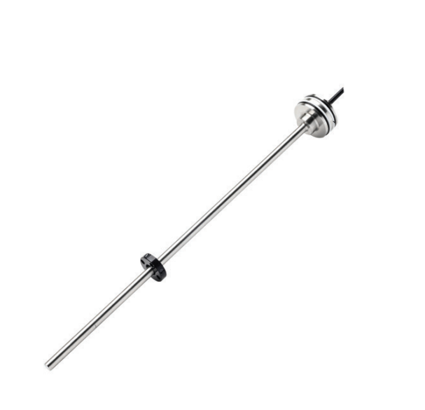
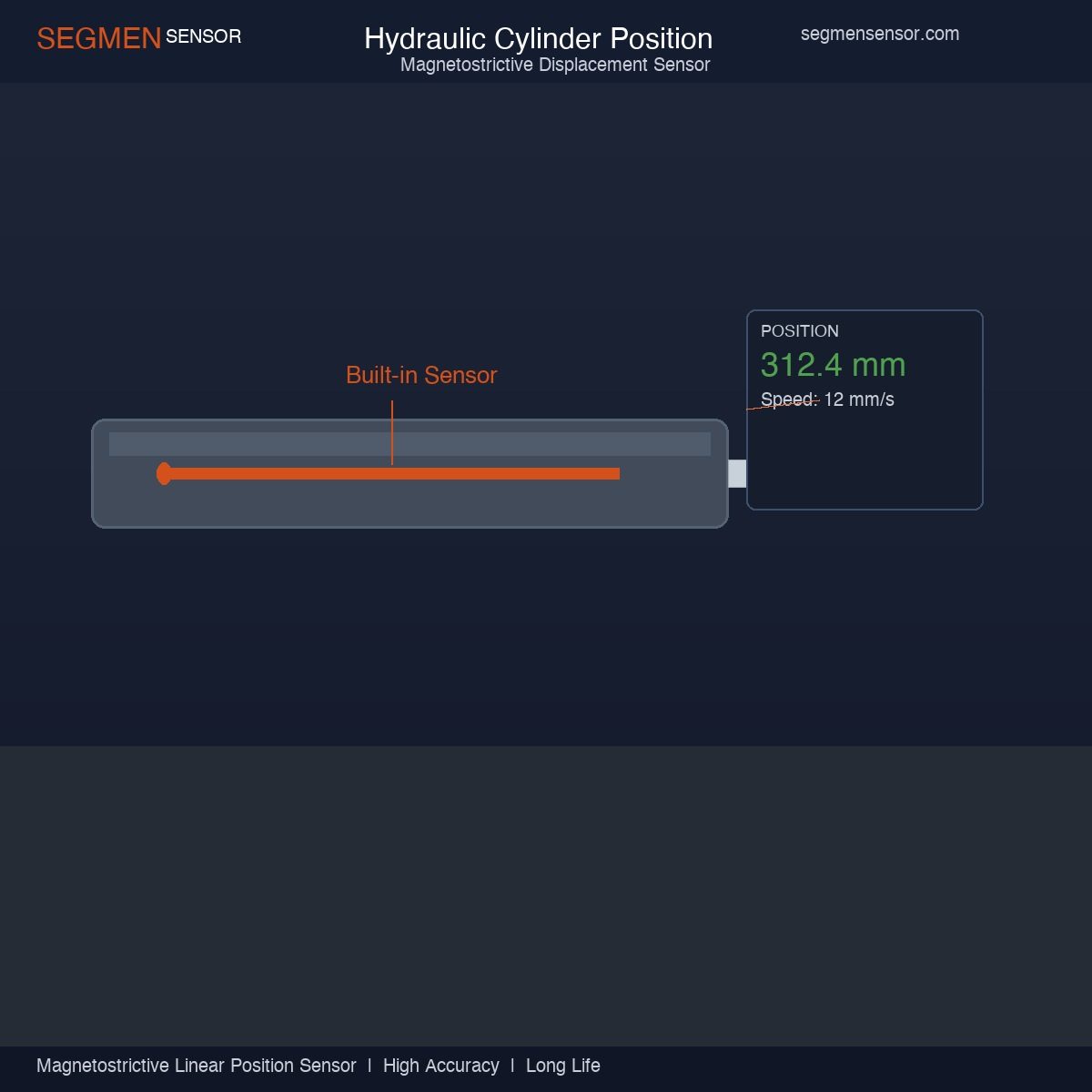
The rod-type sensor installs directly inside the hollow bore of a hydraulic cylinder piston rod. The sensor rod protrudes from a port in the cylinder rear cap, and the position magnet ring mounts inside the hollow piston. As the piston strokes, the magnet moves along the sensor rod inside the sealed cylinder — completely protected from the external environment. The sensor head remains outside the cylinder, connected to the machine control system.
No External Failure Points
Because the sensor is installed inside the cylinder, there are no external position feedback cables, external linear scales, or mechanical linkages that can be damaged by contamination, mechanical impact, or vibration. This is a significant reliability advantage in harsh industrial environments such as presses, forming machines, and mobile hydraulic equipment.
Full Stroke, Real-Time Absolute Position
The sensor provides continuous absolute position feedback across the full cylinder stroke — from 25 mm to 8,000 mm — at update rates up to 5 kHz. The machine controller always knows the exact piston position without any position initialization. This enables precise force-position control, end-of-stroke speed reduction, and synchronization of multiple cylinders.
OEM-Ready Dimensions
SEGMENsensor rod-type magnetostrictive sensors are available in standard rod diameters of φ10 mm, φ12 mm, φ16 mm, and φ18 mm to match standard hydraulic cylinder hollow piston bore dimensions. Custom rod diameters and thread connections are available for OEM programs. The sensors are rated IP68 and compatible with hydraulic oils, cutting fluids, and phosphate-ester fluids.
Magnetostrictive Sensor Output Interfaces
SEGMENsensor magnetostrictive linear position sensors are available with five standard output interfaces, selectable at the time of order. The right choice depends on your control system architecture, cable run length, and required update rate.
4-20 mA Analog Output
The simplest and most universally compatible output. The 4-20 mA current loop signal is proportional to position across the stroke range. 4 mA represents the zero (start) position; 20 mA represents the full stroke. Current loop signals are immune to voltage drop along cable runs, making 4-20 mA reliable at cable runs up to 1,000 m. Resolution is limited by the resolution of the receiving analog input module (typically 12-bit or 16-bit).
0-10 V DC Analog Output
Voltage analog output for short-distance applications where the control system has a high-impedance voltage input. Suitable for cable runs up to approximately 10 m. More susceptible to noise and voltage drop on longer runs than 4-20 mA.
SSI (Synchronous Serial Interface) Digital Output
SSI is a point-to-point synchronous serial protocol used by industrial motion controllers, servo drives, and high-end PLCs. The controller sends clock pulses; the sensor shifts out a 25-bit absolute position word synchronously. SSI provides update rates up to 1 MHz clock frequency and position resolution limited only by the sensor's internal resolution (1 μm). This is the preferred output for high-speed servo press and injection molding position control.
CANopen Fieldbus
CANopen is an open industrial fieldbus protocol widely used in multi-axis machine automation. Multiple magnetostrictive sensors can share a single CANopen network, with each sensor addressable by node ID. The sensor transmits position as a CANopen Process Data Object (PDO) at configurable update intervals or on event/change. Suitable for CNC machines, automated assembly lines, and multi-axis forming equipment.
RS485 Modbus RTU
Modbus RTU over RS485 is the dominant protocol in industrial SCADA systems, tank gauging networks, and process control installations. Up to 32 sensors share a two-wire RS485 bus (up to 247 with repeaters). Position is read from Modbus holding registers using standard function codes. This is the preferred output for liquid level gauging networks and process instrumentation.
Applications Where Magnetostrictive Sensors Excel
Hydraulic Presses, Metal Forming, and Injection Molding
These are the highest-volume applications for rod-type magnetostrictive sensors. Position-controlled hydraulic presses use the sensor for: accurate depth control at ±0.1 mm tolerances; automatic ram speed ramping at end-of-stroke (to reduce impact and noise); multi-point pressure-position profiling; and die protection (stopping the ram if contact is detected at the wrong position). Injection molding machines use the sensor to control screw position during injection, pack, and hold phases. In both applications, SSI output to a servo press controller or PLC motion module is standard.
Liquid Level Measurement in Storage Tanks
Profile-type and cable-type magnetostrictive sensors are used for precise liquid level measurement in process and storage tanks, including interface level detection where two immiscible liquids (e.g., water and oil) are present. A dual-float configuration uses two magnets on a single waveguide: one float rides the upper interface and one rides the lower interface, providing simultaneous level and interface readings. This is significantly more accurate than radar or guided wave radar for short-range level measurements in small tanks (<3 m diameter).
Medical Equipment and Surgical Robotics
Magnetostrictive sensors are used in medical imaging positioning tables, surgical robot linear axes, and rehabilitation equipment where precise, repeatable, non-contact position feedback is required in a clean environment. The non-contact principle and IP67 rating allow the sensor to operate in sterilization environments.
Semiconductor Wafer Handling
In semiconductor wafer handlers, the combination of sub-millimetre absolute position accuracy, non-contact operation (no particle generation), and SSI digital output makes magnetostrictive sensors suitable for linear positioning of wafer carriers and end-effectors in clean room environments.
SEGMENsensor Magnetostrictive Linear Position Sensors
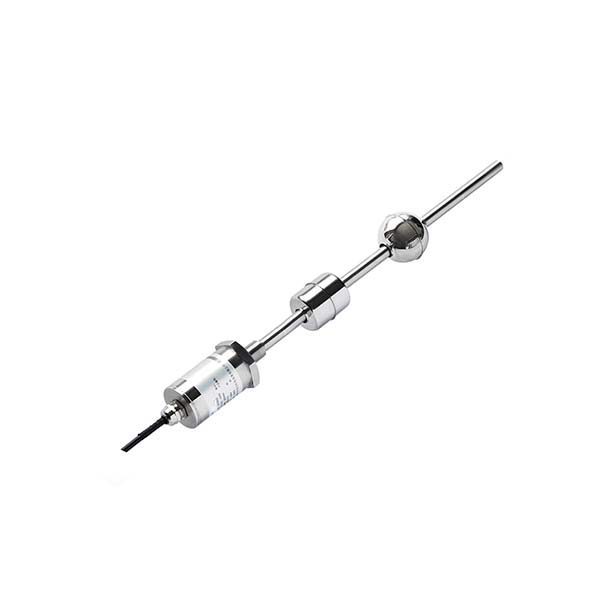
SEGMENsensor designs and manufactures magnetostrictive linear position sensors for industrial OEM customers across hydraulic, process, and automation industries. Our range covers rod-type, profile-type, and cable-type configurations with the full output interface selection described above.
Standard specifications:
- Stroke range: 25 mm – 8,000 mm (standard); custom lengths on request
- Linearity: ±0.05 mm (rod-type), ±0.1 mm (profile/cable type)
- Resolution: 1 μm
- Repeatability: ±0.01 mm
- Output: 4-20 mA, 0-10 V, SSI, CANopen, RS485 Modbus RTU
- Operating temperature: -40°C to +85°C (electronics), -40°C to +105°C (sensing element)
- Protection: IP67 standard, IP68 available for hydraulic cylinder integration
- Hydraulic pressure (rod-type): up to 350 bar sealed versions available
- Certifications: ISO 9001, CE, RoHS, ATEX
- OEM MOQ: 10 pieces; volume pricing from 50 pieces
If you are comparing magnetostrictive and LVDT technology for your application, see our detailed comparison: LVDT vs Magnetostrictive Sensor — Which Should You Specify?
To download product datasheets and dimensional drawings for SEGMENsensor magnetostrictive sensors, visit the magnetostrictive sensor downloads page.
Frequently Asked Questions
A magnetostrictive position sensor works by sending a current pulse along a magnetostrictive waveguide element. At the position of an external permanent magnet (the position element), the interaction between the pulse's magnetic field and the magnet creates a mechanical torsional wave (Wiedemann effect). This torsional wave travels back along the waveguide to the sensing head at a known acoustic velocity (~2,830 m/s). The time from pulse emission to wave arrival is measured with nanosecond precision, and position is calculated as (time × velocity). No mechanical contact occurs between the magnet and the waveguide.
SEGMENsensor magnetostrictive linear position sensors achieve linearity of ±0.05 mm (resolution 1 μm) on standard rod-type sensors and ±0.1 mm on profile/cable types. Repeatability is ±0.01 mm. This accuracy is maintained across the full stroke length — from 25 mm to 8,000 mm — and does not degrade with age since no mechanical contact occurs. The main accuracy factor is the speed of sound in the waveguide, which is temperature-compensated in the sensor electronics.
A rod-type magnetostrictive sensor uses a circular cross-section stainless steel rod that slides through the hollow piston of a hydraulic cylinder or mounts externally via a bracket. It is compact and ideal for cylinder integration. A profile-type (also called "U-channel" or extrusion) sensor has a flat housing mounted externally on a machine frame, with the position magnet sliding along a carrier attached to the moving part. Profile types are used for linear guides, conveyor systems, and external mounting where cylinder integration is not possible.
Yes. Magnetostrictive sensors can support up to 4 position magnets on a single waveguide, providing independent simultaneous position readings for multiple moving parts on one sensor element. This is used in liquid level gauges to simultaneously measure level and interface position (two-float sensors), and in multi-axis pressing and forming machines where multiple cylinders share one sensing element.
For most PLC and SCADA integration: specify 4-20mA analog output for simple applications and long cable runs (up to 1,000 m). Specify SSI (Synchronous Serial Interface) for high-speed, high-resolution digital feedback to motion controllers where 4-20mA resolution is insufficient. Specify RS485 Modbus RTU for industrial SCADA networks. Specify CANopen for multi-axis machine automation with CANopen-based controllers. SEGMENsensor offers all four outputs, with the model code reflecting the output type.
Because the position magnet floats externally along the waveguide without mechanical contact, magnetostrictive sensors have no wearing parts. Service life under normal industrial operating conditions (temperature -40°C to +85°C electronics, IP67 rated) exceeds 20 years. The waveguide element does not wear. The main failure modes are: physical shock damage (exceeding the rated shock resistance), contamination of the magnet guide surface preventing magnet movement, or electronics damage from overvoltage.
SEGMENsensor magnetostrictive linear position sensors are available in standard stroke lengths from 25 mm to 8,000 mm. Custom stroke lengths are available on order. For strokes above 8,000 mm, multi-piece waveguide constructions are possible for special applications (contact the engineering team). The stroke accuracy specification of ±0.05 mm applies across the full stroke regardless of length.
Yes. Rod-type SEGMENsensor magnetostrictive sensors are IP67/IP68 rated and can operate submerged in water, hydraulic oil, hydraulic fluid, and most industrial liquids. The rod-type sensor designed for hydraulic cylinder integration is sealed to IP68 (continuous immersion) and compatible with ISO VG 32–68 hydraulic oils and most phosphate-ester fluids. The position magnet is housed in the piston and also operates in the fluid environment. High-pressure sealing versions are available for cylinder pressures up to 350 bar.