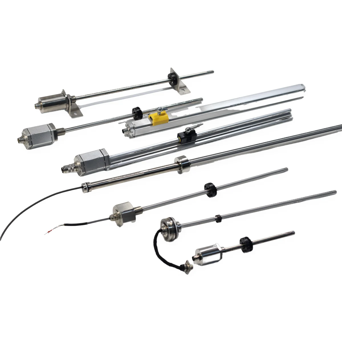
The Wiedemann effect is a magnetomechanical effect: a ferromagnetic wire twists when an electric current flows through it while it is magnetised along its length. It is one form of magnetostriction, the change in shape of a magnetic material when it is magnetised. A current pulse makes a twist only where the axial field is present, so in a magnetostrictive sensor the twist starts exactly at the position magnet and its travel time to the sensor head gives the position.
What causes the Wiedemann effect?
Two magnetic fields acting on the same ferromagnetic wire cause it. The current produces a field that circles the wire; a magnet or coil produces a field along the wire. Their sum is a helical field, and the material strains along that helix, which shears the wire into a twist.
- Circular field from the current. Current I in a wire of radius r produces a field H = I ÷ (2πr) at its surface, circling the axis. On its own it does not twist the wire.
- Axial field from a magnet. A permanent magnet or a coil magnetises the same section of wire along its length.
- Helical sum, helical strain. The two fields add to a helical field. Magnetostriction — defined by the IEC as “reversible deformation of a body due to magnetization” (IEV 121-12-75 ↗) — stretches or shortens the material along that helix, and the result is a twist.
Reverse the current or the axial field and the twist reverses. An alternating current makes the wire oscillate in torsion; a single short pulse makes a single short twist.
What is the formula for the Wiedemann effect?
There is no single engineering formula for the twist angle: in the linear approximation the twist per unit length grows with the current density and with the material’s magnetoelastic coupling (which rises with the axial field), and falls as the shear modulus G rises. For sensor work three exact relations are what matter:
| Relation | Formula | Meaning |
|---|---|---|
| Circular field at the wire surface | H = I ÷ (2πr) | H in A/m, I in A, r in m (Ampère’s law) |
| Torsional wave speed | v = √(G ÷ ρ) | G = shear modulus, ρ = density of the waveguide alloy |
| Position from travel time | x = v × t | t = time from current pulse to wave arrival at the head |
Units are the SI units published by NIST (SI base units, including the ampere and metre) ↗. Because v depends only on G and ρ, it is a constant of the alloy; G changes slightly with temperature, which is why sensor electronics compensate the wave speed.
Worked example: travel time and resolution
- Wave speed in the waveguide: v ≈ 2,800 m/s, so 1 mm of travel takes 1 ÷ 2,800,000 s ≈ 0.357 µs.
- Position magnet 500 mm from the head: t = 0.500 ÷ 2,800 ≈ 179 µs.
- Magnet at the end of an 8,000 mm stroke: t = 8.000 ÷ 2,800 ≈ 2.86 ms, so one measurement cycle on the longest stroke stays below 3 ms.
- A 0.1 µm step in position changes the travel time by 0.1 × 10⁻⁶ ÷ 2,800 ≈ 36 ps, which shows why stable timing and temperature compensation decide the resolution.
- Field example: a 1 A pulse in a wire of 0.5 mm radius gives H = 1 ÷ (2π × 0.0005) ≈ 318 A/m at its surface (illustrative values, not a product specification).
All values above are calculated. Once the sensor converts position to an analogue signal, scale it in the PLC with the 4–20 mA calculator.
How is the Wiedemann effect different from the Joule, Villari and Matteucci effects?
All four are magnetomechanical effects in ferromagnetic materials; they differ in what goes in and what comes out. A magnetostrictive sensor uses two of them: one to launch the wave and one, typically, to detect it.
| Effect | Input | Output | Role in a magnetostrictive sensor |
|---|---|---|---|
| Joule effect (magnetostriction) | Axial magnetisation | Change in length | Basic property of the waveguide alloy |
| Wiedemann effect | Axial field + current | Twist | Launches the torsional wave at the magnet |
| Villari effect (inverse magnetostriction) | Mechanical stress | Change in magnetisation | Typical pickup: the arriving wave changes magnetisation, a coil turns it into a voltage pulse |
| Matteucci effect (inverse Wiedemann) | Twist of a magnetised wire | Induced voltage | Alternative detection principle |
Magnetostriction of electrical steels is a measured material property; IEC sets the measurement method in IEC 60404-17 (magnetostriction characteristics of electrical steel) ↗.
How do magnetostrictive sensors use the Wiedemann effect?
They use it as a self-locating ultrasonic source: the twist can only start where the position magnet is, so measuring when it arrives at the head measures where the magnet is.
- The electronics send a current pulse into the waveguide inside the stainless steel rod or profile.
- At the ring magnet (on the piston, the float or the carriage) the Wiedemann effect launches a torsional wave.
- The wave heading away from the head is absorbed by a damper at the far end, so it does not return as an echo.
- The wave heading to the head is converted back into an electrical pulse by the pickup.
- The time between the two pulses, multiplied by the wave speed, is the absolute position — no homing after power loss and no contact between magnet and waveguide.
The full signal chain, outputs and rod versus profile designs are covered in how a magnetostrictive position sensor works; for the trade-offs against inductive displacement sensing see LVDT vs magnetostrictive sensor.
What limits a Wiedemann-effect measurement in practice?
| Factor | What it does | How it is handled |
|---|---|---|
| Temperature | Changes the shear modulus G and so the wave speed v | Temperature compensation in the electronics; calibration over the stroke |
| Reflections | A wave reflected from the far end would arrive as a false second pulse | Damper at the far end of the waveguide |
| Magnet field | The axial field strength sets the twist amplitude | Use the position magnet specified for the sensor and keep its distance to the rod as specified |
| Housing material | A magnetic housing would screen the axial field from the waveguide | Non-magnetic stainless steel tubes and profiles around the waveguide |
SEGMENsensor magnetostrictive sensors: key data
| Parameter | Value |
|---|---|
| Measuring range | 25–8,000 mm (position and level); SE-LX level series 200–8,000 mm |
| Resolution | Up to 0.1 µm (position sensors) |
| Non-linearity | ±0.01% FS; 10-point calibration |
| Analogue outputs | 4–20 mA 2-wire + HART, 0–10 V, 0–5 V, 0.5–4.5 V |
| Digital outputs | SSI, RS485, TTL, Profinet, CAN, EtherCAT; START-STOP, PWM (per model, confirmed at order) |
| Supply | 24 V DC standard; 12 V and 5 V ranges depending on output and model |
| In-cylinder pressure rating | SGM-PR10: 35 MPa continuous, 70 MPa peak |
| Samples | From 1 pc for qualification; volume per project |
See the full range on the magnetostrictive sensor page, the in-cylinder SGM-PR10 position sensor and the SE-LX20 magnetostrictive level transmitter, which measures level and interface with two floats on one waveguide.
Specifying a magnetostrictive sensor for an OEM project?
Send the stroke or tank height, the output your controller needs, the pressure and temperature, and how the magnet will be mounted. Our engineers will propose the series and options. Qualification samples in 5–7 working days · production 3–5 weeks · FOB China · reply within 24 hours.
Frequently Asked Questions
It is one form of magnetostriction. Plain magnetostriction (the Joule effect) changes the length of a material magnetised along one axis; the Wiedemann effect is the twist that appears when an axial field and the circular field of a current act together.
It is named after the German physicist Gustav Wiedemann, who described in the 19th century how an iron wire carrying current twists when it is magnetised along its length.
The Matteucci effect: twisting a wire that is magnetised along its length induces a voltage between its ends. Many magnetostrictive sensors detect the returning wave with the related Villari effect, in which stress changes the magnetisation sensed by a pickup coil.
Only ferromagnetic materials, such as iron, nickel, cobalt and their alloys. Copper, aluminium and non-magnetic stainless steels do not show it, which is why the waveguide is a magnetostrictive alloy and the protective tube around it is non-magnetic stainless steel.
As a torsional wave at about 2,800 m/s in sensor waveguides, set by v = √(G ÷ ρ) of the alloy. That is about 0.357 µs per millimetre, or about 179 µs for a magnet 500 mm from the head (calculated).
Because every current pulse starts a new wave at the magnet’s current location and the travel time is measured from zero each time. Nothing is counted between measurements, so the sensor reports the true position immediately after power-up, without homing.