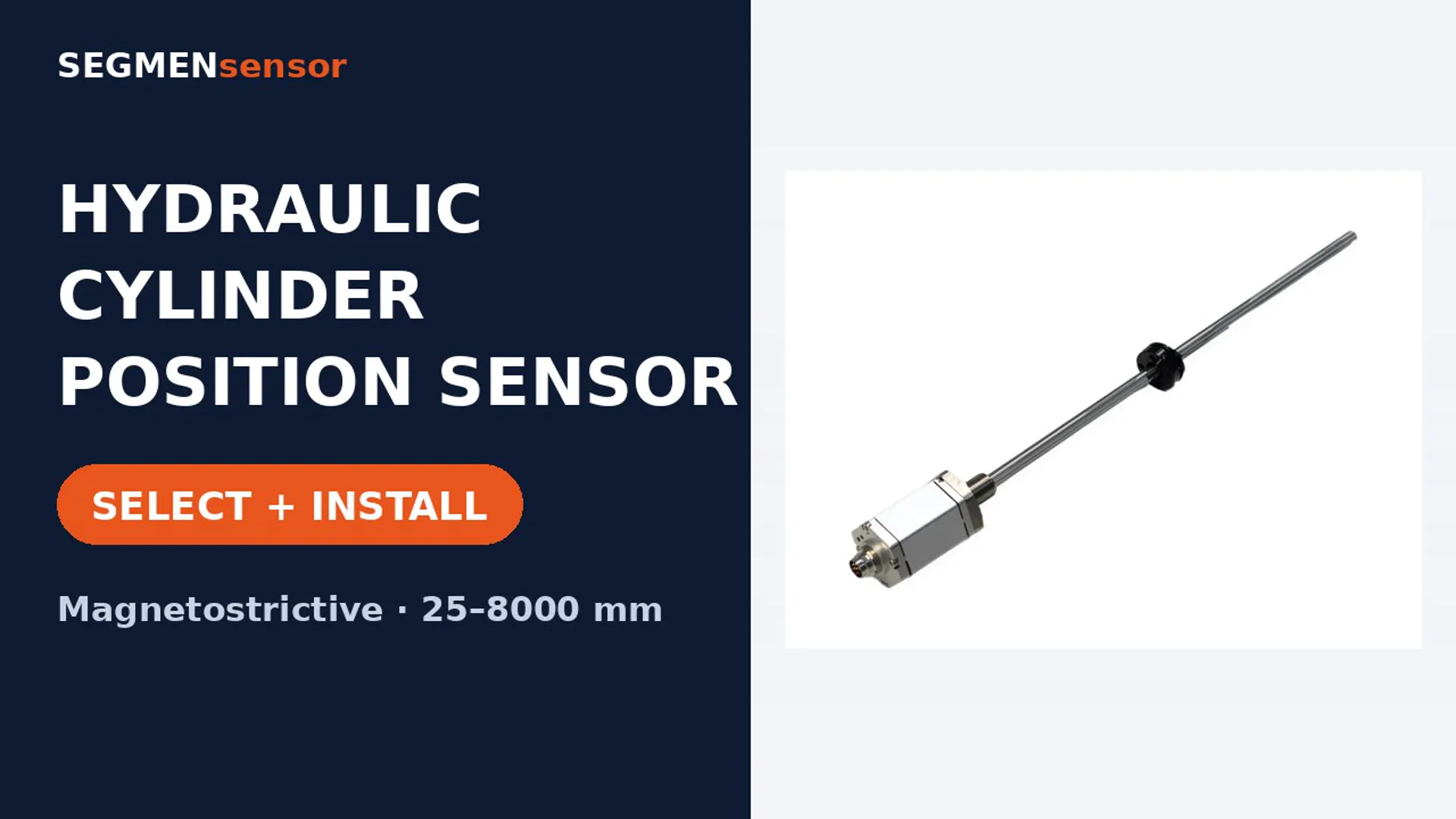
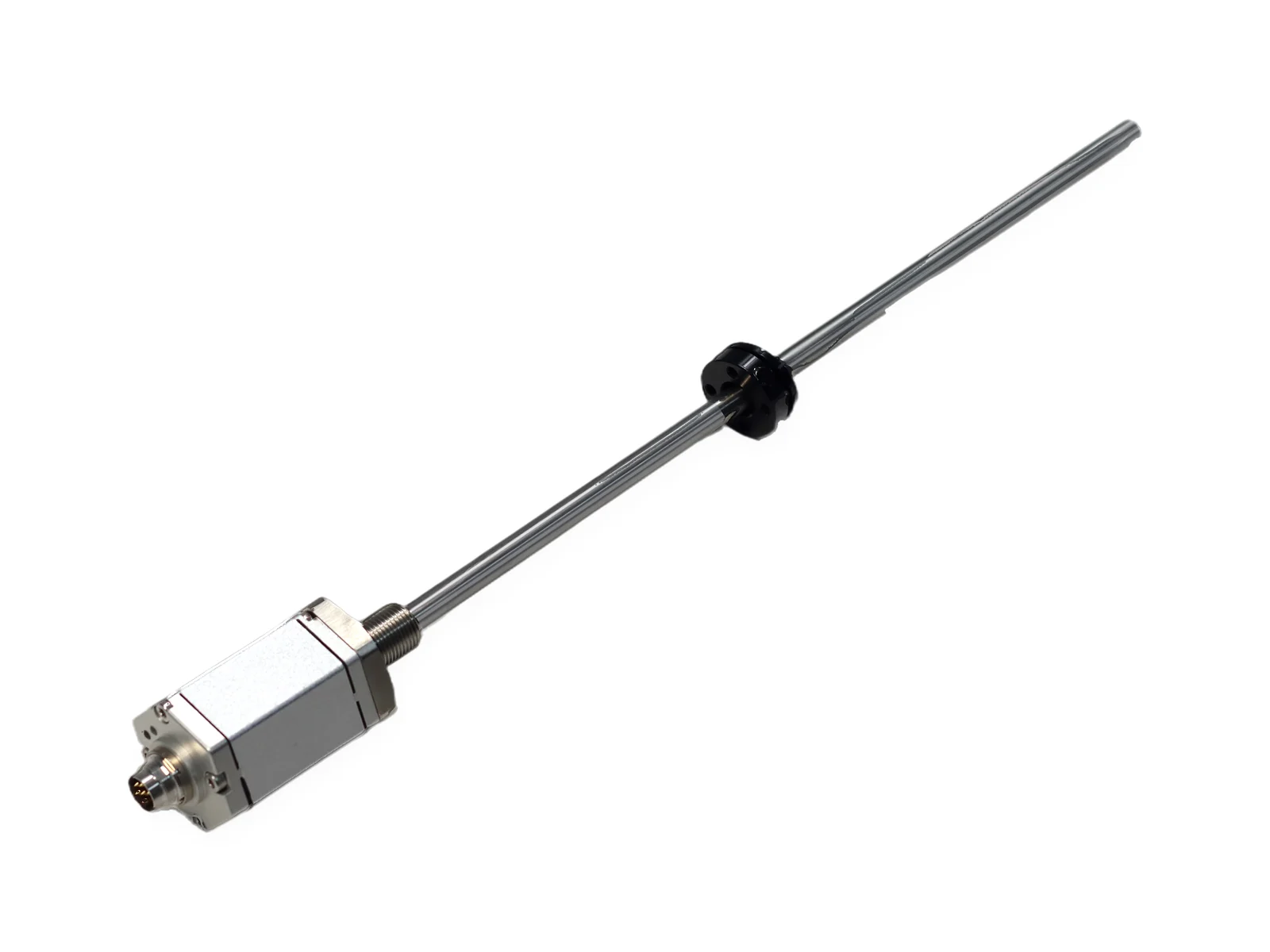
SGM-PR10 is a rod-type magnetostrictive position sensor built into the bore of a hydraulic or pneumatic cylinder. The pressure-resistant tube takes 35 MPa continuous (70 MPa peak), stroke is 25–8000 mm, and the sensor reports absolute piston position as 4–20 mA, 0–10 V, RS485 or SSI with no homing after power loss.
SEGMENsensor SGM-PR10 is an in-cylinder magnetostrictive position sensor: its pressure tube sits in the gun-drilled piston rod, a ring magnet on the piston marks position, and the head reports absolute stroke from 25 to 8000 mm as 4–20 mA, 0–10 V, RS485 or SSI, with no homing after power loss.
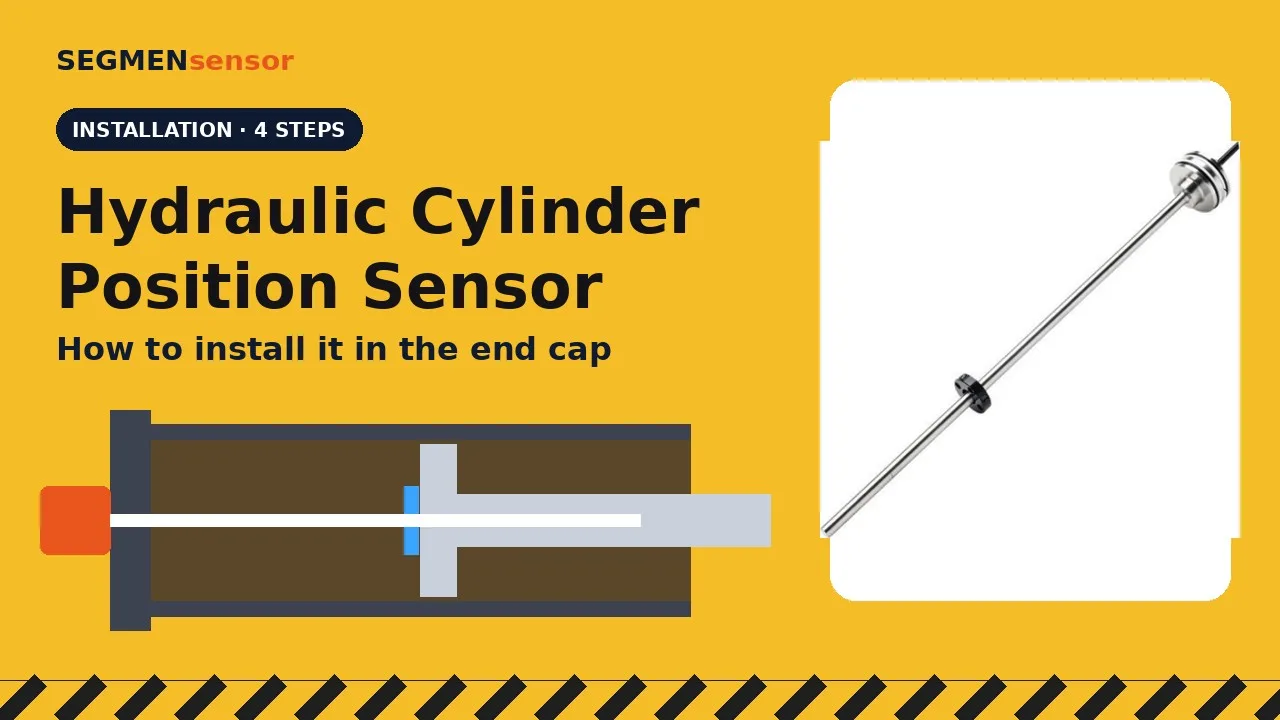
Hydraulic cylinder position sensors: how to choose one, and how to install it. A cylinder position sensor reports the absolute position of the piston. Most use the magnetostrictive principle. The electronics send a current pulse along a waveguide wire. Where it meets the field of the ring magnet on the piston, the wire twists. The twist travels back as a torsional wave. Its travel time gives the absolute position, with no homing after power-up. There are three ways to install. Rear end-cap mounting is the most common: the rod runs inside the drilled piston rod, fully enclosed. External mounting retrofits an existing cylinder without machining the bore. Side or front mounting suits short strokes under 500 mm. Rear end-cap installation, step by step. First, gun-drill the piston rod, so the pressure tube slides in without touching the bore. Next, fit the ring magnet to the piston, with a non-magnetic spacer and non-magnetic screws. Insert the sensor through the threaded port, for example M18×1.5, and seal it with the O-ring. The electronics head stays outside the oil. Connect a shielded cable, and the output follows the piston. Specify the stroke (25–8000 mm) and check the pressure rating: 35 MPa continuous, 70 MPa peak. Choose the output (4–20 mA, 0–10 V, RS485 Modbus or SSI), the mounting thread and the protection class. This is the SGM-PR10, built for direct installation inside hydraulic cylinders. On the production line, rods and flanges are laser-welded, and the return signal is checked on an oscilloscope. Sensors are calibrated on a linear test bench, where software checks the reading along the stroke. SEGMENsensor hydraulic cylinder position sensors. OEM volume supply. Datasheets and quotes at segmensensor.com.
Installing a sensor inside a hydraulic cylinder. The most common method mounts a magnetostrictive sensor through the rear end cap, fully enclosed in the cylinder. Step one: gun-drill the piston rod, so the sensor's pressure tube slides in without touching the bore. Step two: fit the ring magnet to the piston, using a non-magnetic spacer and non-magnetic screws. Step three: insert the sensor through the threaded port and seal it with the O-ring. The electronics head stays outside the oil. Step four: connect a shielded cable and run the cylinder. The output follows the piston, with no homing after power-up. SEGMENsensor in-cylinder sensors: strokes from 25 to 8000 mm, rated to 350 bar. segmensensor.com
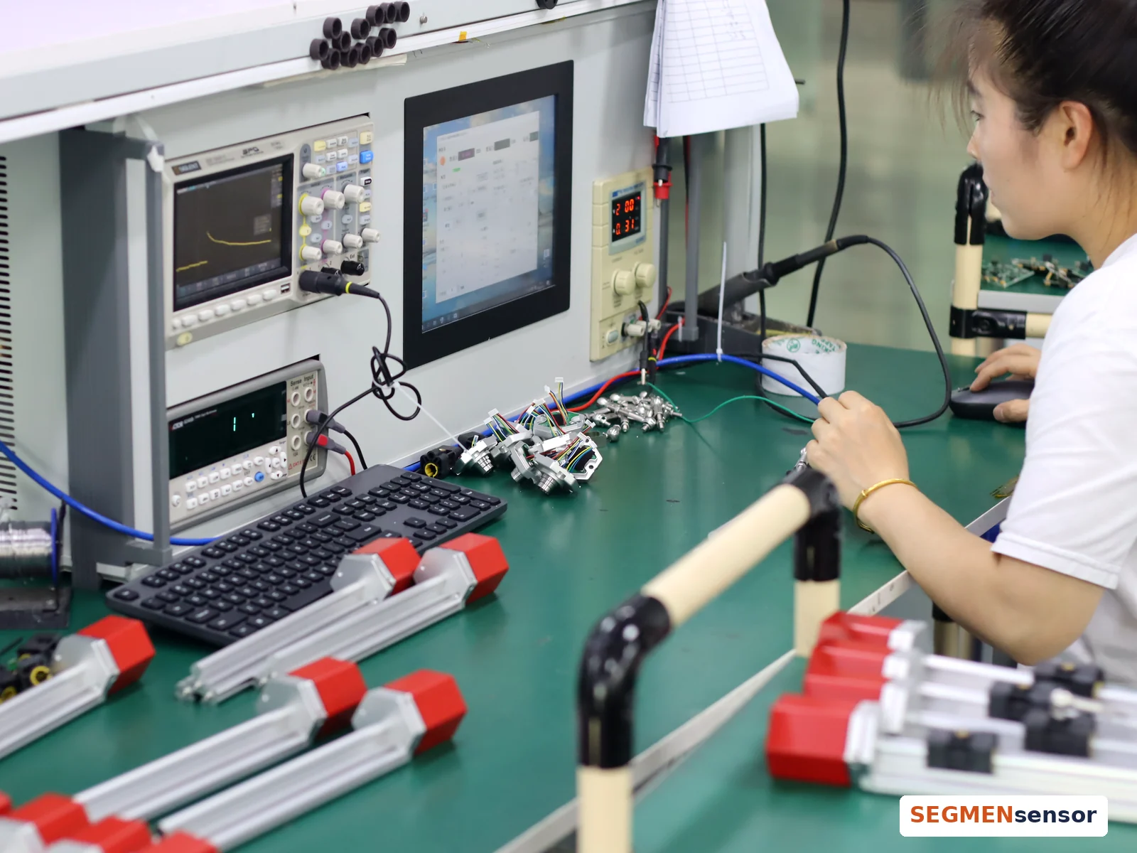
Magnetostrictive position sensors: how SEGMENsensor builds and tests them. It starts with the electronics. Each sensor board is soldered by hand and fitted into the sensor head. The head, cable and connector are assembled on the housing, and heat-shrink sleeves seal the wiring. Rods and flanges are joined by laser welding on a rotary fixture, with a camera to align each seam. The electronics then run on a burn-in rack. Every sensor is tested. The oscilloscope checks the return signal, and a meter checks the output. Each sensor is then calibrated on a linear test bench, where software checks its reading along the stroke. Finally, the nameplate is laser-marked with the model and the company name. Strokes 25–8000 mm · OEM volume supply · Request a quote at segmensensor.com
The SGM-PR10 compact pressure-resistant outer tube is suitable for being built into hydraulic cylinders and air cylinders. Analog output 0-10VDC / 4-20mA / 0-20mA; digital output RS485 / SSI / Profinet (on request). Part number prefix SGM stands for the SEGMENsensor magnetostrictive range; the full ordering code is explained below and in the datasheet.
Updated 2026-10-01 · Values from the SGM-PR10 datasheet, Rev A.
All values from the SGM-PR10 datasheet. Orderable range as listed; longer ranges and special temperature or pressure versions on request.
| Parameter | Value |
|---|---|
| Output type | |
| Analog output | 0-10VDC / 4-20mA / 0-20mA |
| Digital output | RS485 / SSI (Profinet on request) |
| Performance | |
| Measuring range | 25–8000 mm |
| Output signal | 0-20mA (max/min load 0/500Ω), 4-20mA (max/min load 0/500Ω), 0-10V (min load >5KΩ), RS485 (MODBUS RTU), SSI |
| Resolution | 16-bit DA |
| Non-linearity | <±0.01%FS (min ±50um) |
| Repeatability | <±0.001% (min ±5um) |
| Update time | <10ms (depending on range); 1ms (1m<range<2m); 2ms (2m<range<3m); 5ms (3m<range<4m) |
| Operating conditions | |
| Magnet speed | any |
| Operating temperature | -40~+85°C |
| Storage temperature | -55~+85°C |
| Humidity | 90% humidity, no frost forming. |
| Temperature coefficient | <30ppm/°C |
| Protection class | IP67 |
| Pressure rating | 35 MPa (continuous) 70 MPa (peak) |
| Electrical | |
| Electrical connection | Direct cable output or connector |
| Supply voltage | 24VDC (±20%) (standard; 12 V and 5 V ranges depending on output and model) |
| Current consumption | <60mA (varies with measurement range) |
| Reverse-polarity protection | Maximum -30VDC |
| Over-voltage protection | Maximum 36VDC |
| Insulation strength | 500VDC |
| Mounting | |
| Mounting orientation | any |
| Mounting | M18*1.5 or custom-made |
| Position magnet | Ring magnet or float |
| Materials | |
| Sensor head | aluminum alloy |
| Protective tube | 304 stainless steel |
| Mounting flange | 304 stainless steel |
Specifications, wiring, dimension drawings and the complete ordering code on two pages. No registration required.
Need a 3D model or help confirming the right model? Contact our engineers — reply within 24 hours on working days. 3D models (STEP) available on request.

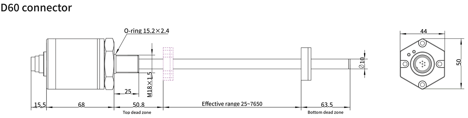
| Dimension | Value (mm) |
|---|---|
| Connector length | 15.5 |
| Head length | 68 |
| Head width | 44 |
| Head height | 50 |
| Mounting thread | M18×1.5 |
| Thread length | 25 |
| O-ring | 15.2×2.4 |
| Rod diameter | Ø10 |
| Top dead zone | 50.8 |
| Bottom dead zone | 63.5 |

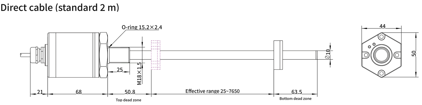
| Dimension | Value (mm) |
|---|---|
| Cable gland length | 21 |
| Head length | 68 |
| Head width | 44 |
| Head height | 50 |
| Mounting thread | M18×1.5 |
| Thread length | 25 |
| O-ring | 15.2×2.4 |
| Rod diameter | Ø10 |
| Top dead zone | 50.8 |
| Bottom dead zone | 63.5 |
| 1 | Analog output + |
| 2 | Analog output - |
| 3 | Reserved for debugging |
| 4 | Reserved for debugging |
| 5 | Input power + |
| 6 | Input power - (GND) |
| 1 | (-)data |
| 2 | (+)data |
| 3 | (+) Clock |
| 4 | (-) Clock |
| 5 | Input power + |
| 6 | Input power - (GND) |
| 7 | NC suspended |
| Green on / red off | Normal operation within the effective range |
| Green off / red on | The magnet is out of the effective measurement range or the magnet cannot be detected. |
| Green off / red flashing | Enter debugging |
Build the part number field by field. Outputs or options listed in the specifications but not in the ordering code are available on request.
| Code | Meaning |
|---|---|
| Mounting | |
| 18 | M18×1.5 |
| 20 | M20×1.5 |
| XX | Custom thread |
| Range | |
| 00025–08000 | 5 digits in mm, 5 mm steps (25–8000 mm) |
| Output | |
| I1F | 4–20 mA, zero at rod end |
| I1R | 4–20 mA reversed (20–4 mA), zero at head |
| I2F | 0–20 mA, zero at rod end |
| I2R | 0–20 mA reversed (20–0 mA), zero at head |
| V1F | 0–10 V, zero at rod end |
| V1R | 0–10 V reversed (10–0 V), zero at head |
| V2F | 0–5 V, zero at rod end |
| V2R | 0–5 V reversed (5–0 V), zero at head |
| R4 | RS485 (Modbus RTU) |
| SS | SSI; append bits+code+resolution µm+direction, e.g. SS25G005F |
| Connection | |
| K16 | M16 connector (analog / RS485 6-pin, SSI 7-pin) |
| C02 … C99 | Direct cable, number = length in m (C02 = 2 m) |
| …X | Suffix X: customer-specified cable |
| Options | |
| (none) | Series standard dead zones |
| Z1 | Short dead zones 30 + 60 mm |
| Z9 | Customer-specified dead zones |
| SGM-PR10-18-00600-I1F-K16 | Rod type, M18×1.5, 600 mm, 4–20 mA, M16 connector |
| Part number | Best for | Range | Output | Protection |
|---|---|---|---|---|
| SGM-PR10 | Hydraulic cylinder position sensor | 25–8000 mm | 4–20 mA / 0–20 mA / 0–10 V / 0–5 V / RS485 / SSI | IP67 |
| SGM-PE10 | Magnetostrictive linear position sensor | 25–8000 mm | 4–20 mA / 0–20 mA / 0–10 V / 0–5 V / RS485 / SSI | IP67 |
| SGM-PR20 | IP68 magnetostrictive position sensor | 25–7500 mm | 4–20 mA / 0–20 mA / 0–10 V / 0–5 V / RS485 | IP68 |
| SGM-PE20 | Slim linear position sensor | 25–4000 mm | 4–20 mA / 0–10 V / RS485 | IP67 |
| SE-PR30 | Intrinsically safe linear position sensor | 25–4000 mm | 0.5–4.5 V / 0–5 V / 4–20 mA / RS485 | IP67 IP68 |
| SGM-PF10 | Flat head magnetostrictive sensor | 25–8000 mm | 4–20 mA / 0–20 mA / 0–10 V / 0–5 V / RS485 | IP68 |
| SGM-PF20 | Compact magnetostrictive sensor | 25–4000 mm | 4–20 mA / 0–10 V / 0.5–4.5 V / 0.25–4.75 V | IP68 |
| SGM-PR40 | Compact rod position sensor | 25–4000 mm | 4–20 mA / 0–20 mA / 0–10 V / 0–5 V / RS485 | IP68 |
| SGM-PR50 | Miniature linear position sensor | 25–4000 mm | 4–20 mA / 0–20 mA / 0–10 V / 0–5 V / RS485 | IP68 |
New to the technology? Read How a magnetostrictive position sensor works. Cylinder drifting under load? See how to check if a hydraulic cylinder is bypassing.
Send the part number, or the stroke, output, mounting and connection you need. Custom ranges, dead zones, cables and magnets are quoted on request.

Send the part number or your application details — an engineer replies within 24 hours on working days with a quotation, lead time and the datasheet.
Tell us your specification — our engineers reply within 24 hours.