To check whether a hydraulic cylinder is bypassing, drive it to the end of stroke, open the opposite port to a container and hold working pressure on the active side. A steady flow of oil from the open port means oil is passing the piston seal. Then isolate the cylinder from its valve and run a drift test to rule out valve leakage.
This guide is for maintenance engineers, hydraulic cylinder builders and machine OEMs who need a repeatable way to separate piston-seal bypass from valve leakage, and who want to catch it earlier with position feedback. The test steps are general workshop practice; the sensor figures come from the SEGMENsensor hydraulic cylinder magnetostrictive sensor and high-pressure inductive proximity sensor pages.
What Does It Mean When a Hydraulic Cylinder Is Bypassing?
It means oil is leaking internally past the piston seal from the high-pressure chamber to the low-pressure chamber. No oil appears outside the cylinder, so the fault is easy to miss: the cylinder still moves, but it loses force at the same pressure, slows down under load and cannot hold a load in position with the valve closed. Oil leaking at the rod gland is a different fault (rod-seal leakage) and is visible from outside.
Common causes are worn or extruded piston seals, a scored or out-of-round barrel, a loose piston retaining nut, contamination that cuts the seal lip, and seals hardened by long running at high oil temperature.
Symptoms, Causes and How to Check Each One
Several faults look like bypassing. Use the table to decide which test confirms or rules out each cause before you strip the cylinder.
| Symptom | Possible cause | How to check |
|---|---|---|
| Rod creeps or the load sinks with the valve centred | Piston-seal bypass, valve spool leakage, leaking load-holding valve, oil cooling and contracting | Drift test with the cylinder isolated from the valve (see below) |
| Cylinder slows down under load but runs normally empty | Piston-seal bypass, worn pump, relief valve set low or leaking | Bypass test at end of stroke; check pump flow and relief setting separately |
| Cylinder cannot reach full force at system pressure | Piston-seal bypass, relief valve set low | Read pressure at the cylinder port during the stall; then bypass test |
| Cylinder barrel or oil runs hotter than usual | Oil throttling across a leaking piston seal or relief valve | Compare barrel temperature with a healthy cylinder on the same machine; bypass test |
| Oil on the rod or at the gland | Rod-seal or wiper leakage (external, not bypassing) | Visual inspection; does not need a bypass test |
| Stroke time is longer than at commissioning | Bypass, pump wear, valve not fully opening | Compare logged stroke time against the commissioning baseline |
How Do You Perform an End-of-Stroke Bypass Test?
You pressurize one side of the piston at the end of stroke and watch the opposite port. Because the piston is held against the end stop, any steady flow out of the open port can only come past the piston seal.
- Make the machine safe. Lower or mechanically support the load, stop the pump, relieve trapped pressure and apply lockout/tagout for hydraulic energy as described in OSHA 29 CFR 1910.147 ↗.
- Drive the cylinder fully home to the end you want to test, usually fully retracted first, so the piston rests on the end stop.
- Disconnect the hose at the opposite port (the rod-end port when testing a retracted cylinder), cap or plug the hose end, and leave the cylinder port open into a clean container.
- Apply pressure to the active side by operating the valve in the same direction, up to normal working pressure but not above the relief setting.
- Watch the open port for 1–2 minutes. A few drops of trapped oil at the start are normal. A steady stream or continuous dripping means the piston seal is bypassing.
- Repeat at the other end of stroke with the connections reversed, because a seal can leak in one direction only.
- Reconnect, bleed air and check for external leaks before returning the machine to service.
Do not plug the open cylinder port during this test. On a single-rod cylinder the cap-end piston area is larger than the rod-end annulus, so pressurizing the cap end against a blocked rod end can raise rod-end pressure above system pressure. Keep the tested port open to the container. General safety requirements for hydraulic systems and their components are set out in ISO 4413 ↗.
How Do You Tell Cylinder Bypassing From Valve Leakage?
Isolate the cylinder from the valve and repeat the drift test. If the rod still creeps with both ports isolated at the cylinder, the leak is inside the cylinder; if it stops, the valve or load-holding valve is the source.
- Hold the load at mid-stroke and mark the rod, or record the position reading.
- Close isolation valves at both cylinder ports, if fitted, or use the load-holding valve mounted on the cylinder.
- Measure the drift over a fixed time, for example 10 minutes, at stable oil temperature.
- Compare with the same test through the directional valve. Drift that disappears with the cylinder isolated points to the valve.
Oil cooling in a closed chamber also contracts and can produce slow drift, so run drift tests at stable operating temperature. Acceptance limits for drift and internal leakage belong to the cylinder manufacturer's test specification; compare against that figure or against a baseline recorded on the same cylinder at commissioning.
Converting drift into leakage (calculated value)
Leakage flow ≈ drift speed × effective piston area. For an 80 mm bore, the full piston area is π/4 × 80² ≈ 5027 mm² (50.3 cm²). A drift of 2 mm/min therefore equals about 50.3 cm² × 0.2 cm/min ≈ 10 mL/min. This is a calculated value for illustration, not a measured limit; use the area of the chamber that is losing oil for your cylinder.
Building cylinders that report their own drift?
Send the bore, stroke, operating pressure, output and annual volume. We propose an SGM in-cylinder sensor or SGI-HP end-position switch and ship qualification samples (1–5 pcs) in 5–7 working days; production lead time and MOQ are confirmed with the quotation, and every inquiry is answered within 24 hours.
How Can Position Sensors Detect Bypassing Earlier?
A position sensor turns a one-off workshop test into a trend the control system can watch. Two signals are useful: drift with the valve centred, and the time the cylinder needs for a full stroke under the same load.
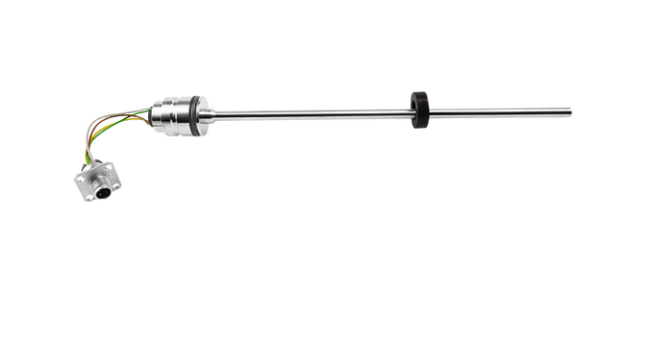
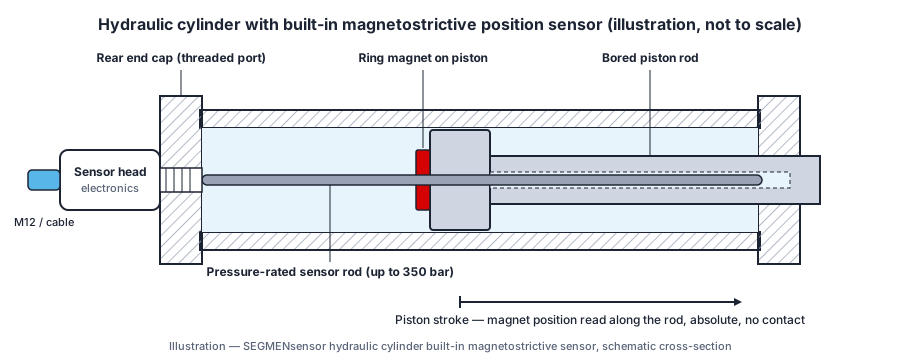
- Drift monitoring with a built-in magnetostrictive sensor. The sensor reports absolute piston position continuously, with no homing after power-up. Log the position at the moment the valve centres and again after a fixed hold time; the difference is the drift. Store the commissioning value and alarm when drift rises above an agreed multiple of it. How the measurement works is explained in how a magnetostrictive position sensor works.
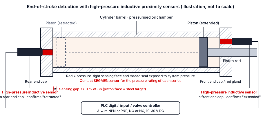
- Stroke-time monitoring with end-position switches. High-pressure inductive proximity sensors in the end caps switch when the piston arrives. The PLC measures the time from the valve command to the switch signal; a stroke time that grows over weeks at the same load and oil temperature is an early sign of bypass or pump wear. See end-of-stroke detection in hydraulic cylinders.
- Speed under load from the position signal. Differentiating the position reading gives rod speed. A cylinder that reaches normal speed empty but slows clearly under load matches the bypass pattern in the symptom table.
These sensors report position and end position for control and condition monitoring. They are standard components with no SIL or PL rating and do not replace the cylinder manufacturer's leakage test or a safety-rated load-holding function.
Sensor Options for Cylinder Monitoring
The table lists published figures for the SEGMENsensor sensors most often built into hydraulic cylinders for position and end-position feedback.
| Sensor | What it measures | Published figures |
|---|---|---|
| SGM-PR10 in-cylinder magnetostrictive | Continuous absolute piston position (drift, speed) | 25–8000 mm; non-linearity <±0.01% FS (min. ±50 µm); 4-20 mA, 0-10 V, RS485 Modbus RTU, SSI standard; IP67 |
| SGM-PF10 in-cylinder magnetostrictive | Continuous absolute piston position (drift, speed) | 25–8000 mm; non-linearity <±0.01% FS (min. ±50 µm); IP68 |
| SGM-PF20, SGM-PR40, SGM-PR50 | Continuous absolute piston position | 25–4000 mm; IP68 |
| In-cylinder pressure tube (SGM series) | Pressure rating of the part inside the bored rod | 35 MPa (350 bar) continuous, 70 MPa peak; supply 24 V DC (±20%) standard |
| SGI-HP high-pressure proximity sensor | End of stroke (stroke time, arrival) | M8 and M12 rated 500 bar; M18 hydraulic-cylinder type in 250, 350, 500, 800 and 1000 bar grades; IP67 / IP69K; 1 kHz switching frequency |
Proximity switches are specified under IEC 60947-5-2 ↗. Pressure, temperature and connector combinations are confirmed per project.
Download the one-page datasheet (PDF)
Ranges, outputs, supply voltage, pressure and temperature limits, IP rating, dimensions and ordering codes for the sensors above. No registration required.
More documents: magnetostrictive downloads · proximity sensor downloads
Factory Supply for Cylinder Builders
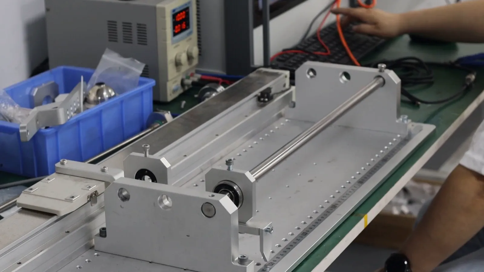
SEGMEN (Shenzhen) Industrial Development Co., Ltd. was founded in Shenzhen in 2019; its engineering team brings more than 20 years of sensor experience and supplies 200+ OEM customers in 30+ countries. Magnetostrictive sensors are calibrated on a linear test bench over the full stroke. Quality is managed under ISO 9001:2015, and products carry CE, RoHS 3 and UKCA, with ATEX/IECEx options and UL on selected models. Orders are quoted FOB China with 100% T/T in advance and a 12-month warranty.
FAQ
General questions
It means oil leaks internally past the piston seal from the pressurized chamber to the other chamber. The cylinder loses force, slows down under load and drifts with the valve closed, while no oil is visible outside.
Drive the cylinder to the end of stroke, disconnect and cap the hose at the opposite port, leave that cylinder port open into a container and apply working pressure to the active side. A steady flow from the open port means the piston seal is bypassing. Repeat at the other end of stroke.
No. On a single-rod cylinder the cap-end piston area is larger than the rod-end annulus, so pressurizing the cap end against a blocked rod end can raise rod-end pressure above system pressure. Keep the tested port open to a container.
Isolate the cylinder at its ports and repeat the drift test. If the rod still creeps with the cylinder isolated, the leak is inside the cylinder; if the drift stops, the directional valve or load-holding valve is leaking.
The acceptable figure comes from the cylinder manufacturer's test specification and the machine's duty. In practice, record drift at commissioning at stable oil temperature and treat a clear rise against that baseline as a reason to run the bypass test.
Procurement Q&A
An in-cylinder magnetostrictive sensor such as SGM-PR10 or SGM-PF10. It reports absolute piston position over 25–8000 mm with non-linearity below ±0.01% FS (min. ±50 µm), and its pressure tube is rated 35 MPa (350 bar) continuous.
Send the bore and rod diameter, stroke, operating and peak pressure, oil temperature, output signal, supply voltage, connector and annual volume. A written quotation follows within 24 hours on working days.
Qualification samples of 1–5 pcs ship in 5–7 working days. Production lead time and MOQ are confirmed with the quotation, based on your annual volume.
References
- OSHA 29 CFR 1910.147 — The control of hazardous energy (lockout/tagout) ↗
- ISO 4413 — Hydraulic fluid power: general rules and safety requirements ↗
- IEC 60947-5-2 — Proximity switches ↗
Related reading: Hydraulic cylinder magnetostrictive sensors · High-pressure proximity sensors · Hydraulic cylinder proximity sensors for high pressure and hot oil · End-of-stroke detection in hydraulic cylinders
Last updated: 29 October 2026. Test steps describe general workshop practice; follow the cylinder manufacturer's instructions and your site safety procedures. Specifications reflect SEGMENsensor product pages and datasheets at the time of writing.