Magnetostrictive Position Sensor for Hydraulic Cylinders — SGM-PR10 Series, 35 MPa, SSI / 4-20mA
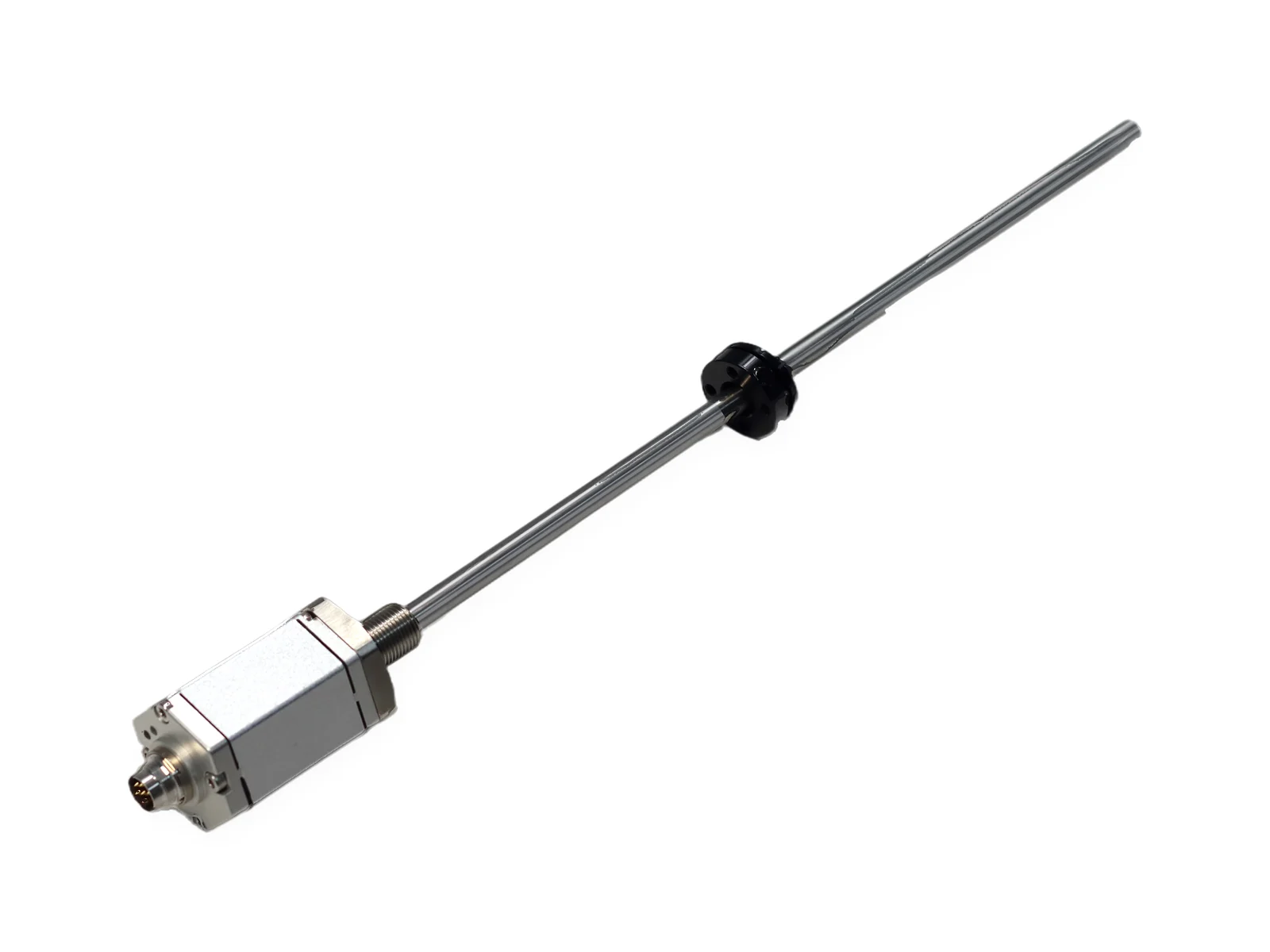
SEGMENsensor magnetostrictive linear position sensors are designed for direct installation inside hydraulic cylinders, providing absolute position feedback on ram extension. Welded into the cylinder end-cap or rear port, the sensing rod extends through the cylinder bore. Pressure tube rated 35 MPa (350 bar) continuous, 70 MPa peak. Series: SGM-PR10 (25–8000 mm), SGM-PF10, SGM-PF20, SGM-PR40, SGM-PR50. Output: 4-20mA, 0-10V, RS485, SSI (SGM-PR10). Non-linearity <±0.01% FS. IP67/IP68, CE certified, OEM programs, samples 1–5 pcs in 5–7 days.
A SEGMENsensor hydraulic cylinder position sensor is a magnetostrictive sensor whose pressure tube runs inside the gun-drilled piston rod while a magnet on the piston marks the stroke. It gives absolute ram position with no homing after power-up; five SGM in-cylinder series cover 25–8000 mm and pressures of 35 MPa continuous.
The pressure tube is rated 35 MPa (350 bar) continuous and 70 MPa peak.
SGM-PR10 and SGM-PF10 cover 25–8000 mm; SGM-PF20, SGM-PR40 and SGM-PR50 cover 25–4000 mm.
Non-linearity is below ±0.01% FS (min. ±50 µm) on SGM-PR10 and SGM-PF10.
Outputs are 4-20 mA, 0-20 mA, 0-10 V and RS485 Modbus RTU; SSI is standard on SGM-PR10.
Protection is IP67 (SGM-PR10) or IP68 (SGM-PF10, PF20, PR40, PR50), and supply is 24 V DC (±20%) (standard; 12 V and 5 V ranges depending on output and model).
Last updated · SEGMENsensor Engineering Team
Watch: choosing and installing a hydraulic cylinder position sensor
Hydraulic Cylinder Position Sensor: Selection and Installation GuideHow a magnetostrictive cylinder sensor measures absolute position, the three mounting options, rear end-cap installation step by step, and what to specify: stroke 25–8000 mm, 35 MPa continuous, output, thread and protection.
Hydraulic cylinder position sensors: how to choose one, and how to install it. A cylinder position sensor reports the absolute position of the piston. Most use the magnetostrictive principle. The electronics send a current pulse along a waveguide wire. Where it meets the field of the ring magnet on the piston, the wire twists. The twist travels back as a torsional wave. Its travel time gives the absolute position, with no homing after power-up. There are three ways to install. Rear end-cap mounting is the most common: the rod runs inside the drilled piston rod, fully enclosed. External mounting retrofits an existing cylinder without machining the bore. Side or front mounting suits short strokes under 500 mm. Rear end-cap installation, step by step. First, gun-drill the piston rod, so the pressure tube slides in without touching the bore. Next, fit the ring magnet to the piston, with a non-magnetic spacer and non-magnetic screws. Insert the sensor through the threaded port, for example M18×1.5, and seal it with the O-ring. The electronics head stays outside the oil. Connect a shielded cable, and the output follows the piston. Specify the stroke (25–8000 mm) and check the pressure rating: 35 MPa continuous, 70 MPa peak. Choose the output (4–20 mA, 0–10 V, RS485 Modbus or SSI), the mounting thread and the protection class. This is the SGM-PR10, built for direct installation inside hydraulic cylinders. On the production line, rods and flanges are laser-welded, and the return signal is checked on an oscilloscope. Sensors are calibrated on a linear test bench, where software checks the reading along the stroke. SEGMENsensor hydraulic cylinder position sensors. OEM volume supply. Datasheets and quotes at segmensensor.com.
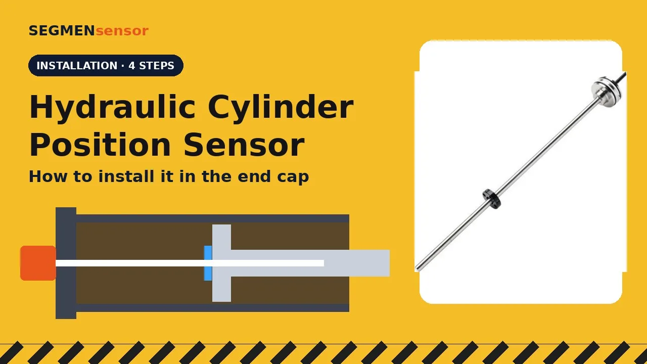
Installing a Position Sensor in a Hydraulic CylinderOne-minute animation of rear end-cap installation of a magnetostrictive position sensor: gun-drilled piston rod, ring magnet with non-magnetic spacer, threaded port with O-ring seal, shielded cable and absolute position output.
Installing a sensor inside a hydraulic cylinder. The most common method mounts a magnetostrictive sensor through the rear end cap, fully enclosed in the cylinder. Step one: gun-drill the piston rod, so the sensor's pressure tube slides in without touching the bore. Step two: fit the ring magnet to the piston, using a non-magnetic spacer and non-magnetic screws. Step three: insert the sensor through the threaded port and seal it with the O-ring. The electronics head stays outside the oil. Step four: connect a shielded cable and run the cylinder. The output follows the piston, with no homing after power-up. SEGMENsensor in-cylinder sensors: strokes from 25 to 8000 mm, rated to 350 bar. segmensensor.com
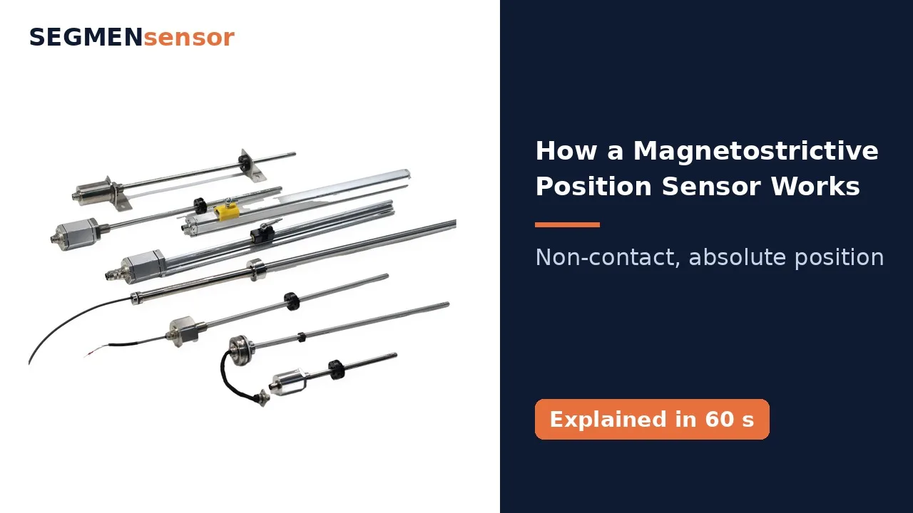
How a Magnetostrictive Position Sensor WorksOne-minute animation of the magnetostrictive time-of-flight principle: current pulse, Wiedemann-effect twist at the position magnet, torsional wave back to the head, position = wave speed × time.
How does a magnetostrictive sensor measure position without contact? Inside the stainless steel rod runs a thin waveguide wire. A ring magnet moves with the piston, the float, or the carriage. First, the electronics send a short current pulse along the wire. The pulse creates a circular magnetic field. Where that field meets the field of the magnet, the wire twists. This is the Wiedemann effect. The twist travels back to the head as a torsional wave, at about two thousand eight hundred metres per second, while a timer measures the travel time. Position equals wave speed times time. The result is absolute position, with no contact and no wear. SEGMENsensor magnetostrictive sensors cover strokes from twenty-five to eight thousand millimetres. Learn more at segmensensor.com.
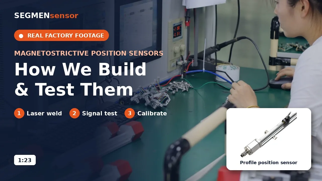
Magnetostrictive Position Sensors: Production and TestingReal production footage of SEGMENsensor magnetostrictive position sensors: electronics assembly, laser welding of rods and flanges, burn-in, signal test on an oscilloscope, calibration on a linear test bench and laser-marked nameplates.
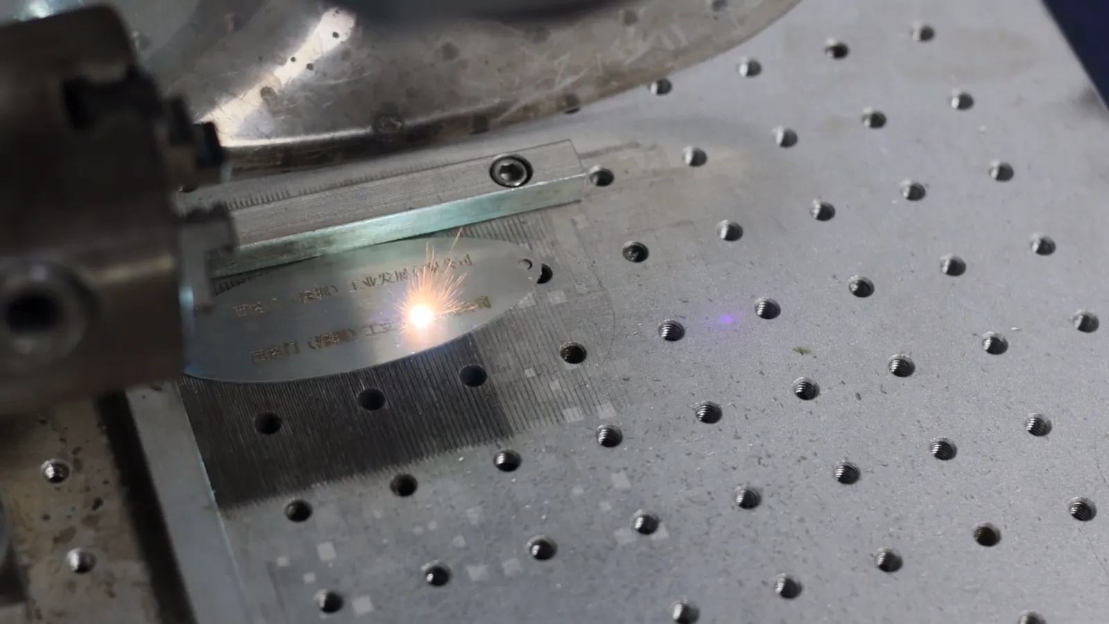
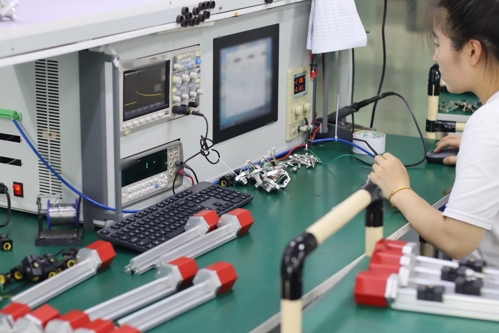
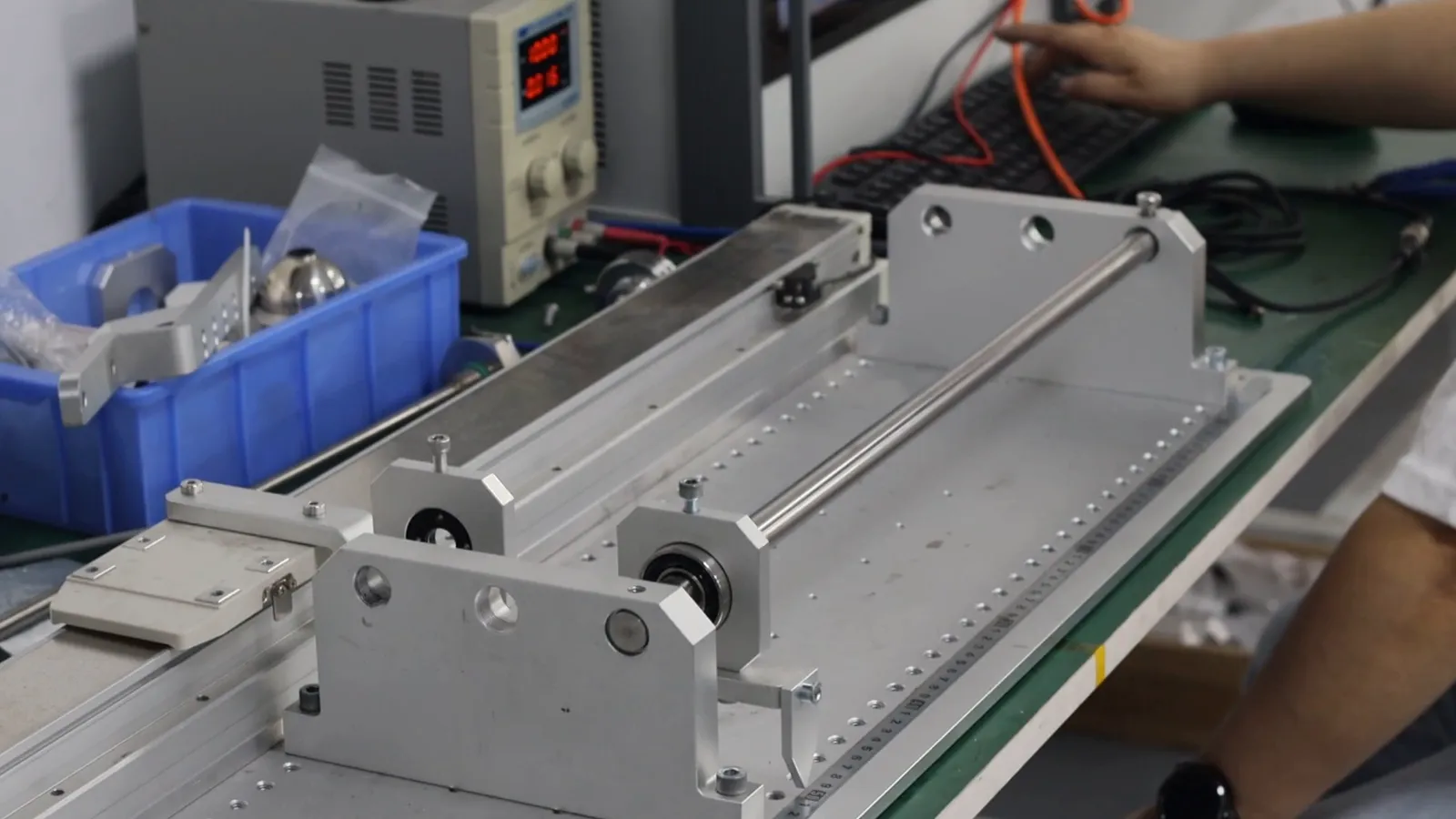
Magnetostrictive position sensors: how SEGMENsensor builds and tests them. It starts with the electronics. Each sensor board is soldered by hand and fitted into the sensor head. The head, cable and connector are assembled on the housing, and heat-shrink sleeves seal the wiring. Rods and flanges are joined by laser welding on a rotary fixture, with a camera to align each seam. The electronics then run on a burn-in rack. Every sensor is tested. The oscilloscope checks the return signal, and a meter checks the output. Each sensor is then calibrated on a linear test bench, where software checks its reading along the stroke. Finally, the nameplate is laser-marked with the model and the company name. Strokes 25–8000 mm · OEM volume supply · Request a quote at segmensensor.com
Made and tested in our factory
Laser welding of magnetostrictive sensor rods and flangesMagnetostrictive sensor signal test stationLinear test bench for calibration over the full stroke
Every unit is tested before shipment. Photos from our own production and test lines.
What is a Magnetostrictive Position Sensor for Hydraulic Cylinders?
A magnetostrictive position sensor for hydraulic cylinders provides absolute, non-contact linear position measurement of the cylinder ram (piston rod). The sensor consists of a stainless steel sensing rod installed through the center of the hydraulic cylinder piston, and a position magnet mounted in the piston. The waveguide inside the rod uses the magnetostrictive effect — a torsional ultrasonic pulse returns to the head electronics when the magnetic field of the piston magnet intersects the current pulse. Time-of-flight measurement gives absolute position with non-linearity <±0.01% FS (SGM-PR10), no re-homing required, even after power loss.
Technical Specifications
Hydraulic Cylinder Magnetostrictive Sensor — Full Spec Table
All parameters for SEGMENsensor in-cylinder magnetostrictive rod sensors. Custom stroke, output interface, and connector on request.
Parameter
Specification
Measurement Principle
Magnetostrictive, absolute (no homing after power-up)
Samples 1–5 pcs for qualification; volume per project
Lead Time
Confirmed with the quotation
Certifications
CE, RoHS
Download the magnetostrictive position sensor datasheet (PDF)
Stroke range 25–8000 mm, rod and profile housings, output options, linearity and repeatability, supply voltage, connectors, rod pressure rating, dimensions and the ordering code. No registration required.
Three Installation Options for Hydraulic Cylinder Sensors
SEGMENsensor magnetostrictive sensors support rear-port, external, and side-mount installation to cover new-build and retrofit cylinder designs.
🔩
Rear-End Installation (Most Common)
Sensor rod inserted through threaded port in cylinder end cap
Rod passes through hollow piston center bore
Position magnet ring mounted in piston bore around rod
Best for new cylinder designs — compact, fully enclosed, no external exposure
Process seal at end-cap port only; no rod sealing required
🔧
External Retrofit Installation
Sensor head mounted externally on cylinder head face
Sensor rod fixed at cylinder head, rod tip attached to piston rod end
Suitable for retrofitting existing cylinders with no bore modification
No cylinder body machining required
Protective sleeve recommended in dirty or high-debris environments
📐
Side / Front-End Cap Installation
Sensor mounted through side port or front end cap
Suited for short-stroke cylinders (<500 mm)
Common in hydraulic fixtures, clamping cylinders, and mold tooling
Compact head profile fits confined installation spaces
Available with angled connector for tight clearances
Applications
Hydraulic Cylinder Position Measurement — Industry Applications
Absolute position feedback in hydraulic systems across industrial, mobile, and process machinery — from injection molding to mining equipment.
🏭
Injection Molding Machines
Clamping force position control, mold open/close absolute feedback for repeatable cycle precision.
🚜
Mobile Hydraulics
Excavator boom, arm, and bucket position sensing; crane luffing and outrigger extension control.
⚙️
Industrial Press
Hydraulic press ram absolute position control; combined force-position feedback in forming presses.
📏
Forming & Bending
CNC press brake back-gauge positioning, tube bending ram position for repeatable bend angle.
🔩
Die Casting
Shot sleeve position feedback, intensifier ram position monitoring for casting quality control.
🪵
Wood Processing
Log saw feed position, veneer lathe hydraulic positioning for accurate cut dimension control.
⛏️
Mining Equipment
Roof support jack position, longwall shearer hydraulic position in underground mining systems.
🌾
Agricultural Equipment
Tractor 3-point hitch position control, header height control for precision agricultural machinery.
Technology Comparison
Which hydraulic cylinder position sensor technology fits your machine?
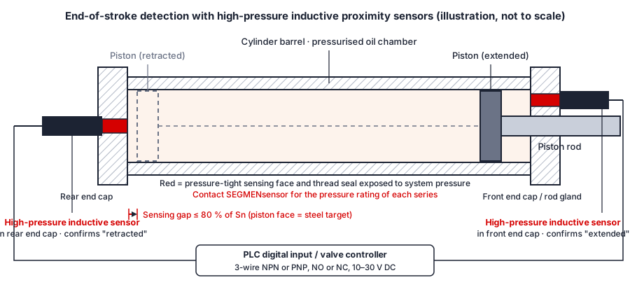
Choose in-cylinder magnetostrictive sensing when the controller needs continuous absolute position; choose end-of-stroke proximity switches when it only needs to know that the cylinder has reached its end positions. The table compares the four sensing approaches cylinder builders usually evaluate. SEGMENsensor values are taken from the specification table on this page and from our high-pressure inductive proximity sensor series page; the other rows describe the technology in general terms, not any specific product.
Hydraulic cylinder position sensing technologies compared. Confirm every value for a specific model against its datasheet.
Criterion
In-cylinder magnetostrictive (SGM series)
External cable-extension (draw-wire)
In-rod inductive linear sensor
End-of-stroke proximity switches (SGI-HP)
Signal
Continuous absolute position, no homing after power-up
Continuous position
Continuous position
Discrete on/off at the two end positions only
Mounting
Through a threaded port in the rear end cap (M18×1.5 or custom thread)
Sensing element fully enclosed; IP67 (SGM-PR10) or IP68 (SGM-PF10, PF20, PR40, PR50)
Cable and drum exposed; guard needed on mobile machines
Sensing element enclosed
Sensing face inside the cylinder; connector outside
Typical use
Servo and proportional axes, synchronised cylinders, presses
Retrofit and test rigs where drilling is not allowed
Mobile-machine cylinders needing continuous position
End-position confirmation, interlocks, sequence control
End-of-stroke sensing: two proximity switches report only the end positions, while an in-cylinder magnetostrictive sensor reports every position along the stroke.
How do you install a position sensor in a hydraulic cylinder?
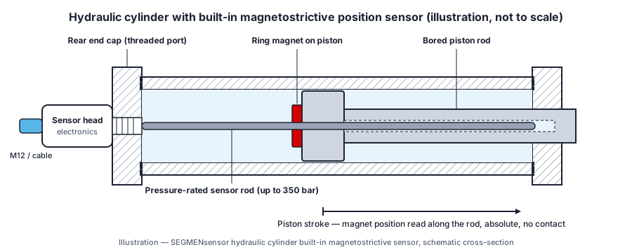
You install an in-cylinder magnetostrictive sensor by screwing its flange into a threaded port in the rear end cap, so the pressure tube slides into a gun-drilled bore in the piston rod while a ring magnet in the piston moves along it. The electronics head stays outside the pressure zone. The steps below follow that rear-end method.
Rear-end installation: sensor head outside the end cap, pressure tube inside the gun-drilled piston rod, ring magnet fixed in the piston.
Fix the stroke and series. SGM-PR10 and SGM-PF10 cover 25–8000 mm; SGM-PF20, SGM-PR40 and SGM-PR50 cover 25–4000 mm. Check the null and dead zones on the series drawing, because the pressure tube is longer than the measuring stroke.
Machine the end-cap port. Cut the thread named in the ordering code (M18×1.5, M20×1.5 on SGM-PR10, or a custom thread) and the O-ring sealing face shown on the datasheet drawing. Many cylinder builders lay out sensor ports in the style of the metric O-ring ports defined in ISO 6149-1; always check the flange and O-ring dimensions against the SEGMENsensor drawing.
Gun-drill the piston rod. Take the bore diameter and minimum depth from the series drawing, so the tube never touches the bottom of the bore at full retraction. Deburr and flush all chips out of the bore before assembly.
Fit the ring magnet in the piston. Use the matched magnet listed in the datasheet and follow the magnet mounting drawing. Keep ferrous screws and spacers away from the magnet so they do not distort its field.
Insert the sensor and seal the port. Lubricate the O-ring with the cylinder's hydraulic oil, slide the pressure tube through the piston and magnet, and tighten the flange as specified on the datasheet drawing. The tube is rated 35 MPa (350 bar) continuous and 70 MPa peak; size the cylinder's pressure peaks against that rating.
Wire and power the head. The standard supply is 24 V DC (±20%), with 12 V and 5 V ranges depending on output and model. Use shielded cable and follow the pin table in the datasheet for 4-20 mA, 0-10 V, RS485 or SSI. Choose a connector or cable gland that keeps the head's IP67 or IP68 rating; the IP code is defined in IEC 60529.
Check the output before the cylinder goes into the machine. Stroke the cylinder to both ends at low pressure and confirm that the signal follows the full stroke in the right direction, then pressure-test the cylinder.
For retrofits where the rod cannot be drilled, see the external retrofit option above, or use end-of-stroke proximity switches if only end positions are needed. A one-minute animation of these steps is in the installation video.
Request qualification samples for your cylinder
Qualification samples (1–5 pcs) ship in 5–7 working days. Production lead time and MOQ are confirmed with the quotation, planned around your annual volume. Send the stroke, port thread, pressure and output, and our engineers reply within 24 hours.
Technical and commercial questions on mounting, pressure ratings, output interfaces, and OEM supply. Ordering terms are covered in our guide to magnetostrictive sensor lead time and MOQ.
How does a magnetostrictive sensor mount inside a hydraulic cylinder?
The most common installation is through the cylinder rear end cap: the flange of the sensor screws into a threaded port in the end cap (M18×1.5 or M20×1.5 on SGM-PR10, per ordering code), and the pressure tube extends into a gun-drilled bore in the piston rod. A ring magnet is fixed in the piston around the tube. As the piston strokes, the magnet moves along the stationary tube and the electronics head reports its absolute position. The electronics head stays outside the pressure zone.
What pressure rating do I need for a hydraulic cylinder position sensor?
The in-cylinder SGM-PR10, SGM-PF10, SGM-PF20, SGM-PR40 and SGM-PR50 have a pressure tube rated 35 MPa (350 bar, about 5,000 PSI) continuous and 70 MPa peak, according to their datasheets. This covers most industrial hydraulic systems. Always state the nominal and peak system pressure when requesting a quote so we can confirm the series and mounting.
What is SSI output and why is it used in hydraulic cylinder sensors?
SSI (Synchronous Serial Interface) is a point-to-point serial interface used by absolute encoders and magnetostrictive sensors. It transmits the absolute position as a binary or Gray code word over differential clock and data pairs. Compared with analog, it is less sensitive to electrical noise and does not drift over cable length. SSI is a standard output on SGM-PR10 and available on request on SGM-PF10; word length, code and resolution are set in the ordering code (e.g. SS25G005F).
Can the same sensor output both SSI and 4-20mA simultaneously?
Each sensor has the output selected in its ordering code: 4-20mA, 0-20mA, 0-10V, 0-5V, RS485 Modbus RTU or SSI (SGM-PR10; on request on SGM-PF10). For two separate analog signals, the profile SGM-PE20 offers a dual-channel analog output. Tell us what the servo drive and the PLC need and we will propose a configuration.
What position magnet do I use with a hydraulic cylinder magnetostrictive sensor?
SEGMENsensor supplies matched position magnets for each series — a ring magnet for in-cylinder mounting, or a float for level use, as listed in the datasheet. The magnet is fixed in the piston bore around the pressure tube. Keep ferrous parts away from the magnet so they do not distort its field, and follow the magnet mounting drawing in the series datasheet.
What is the accuracy of a magnetostrictive sensor in a hydraulic cylinder application?
Datasheet values: SGM-PR10 and SGM-PF10 non-linearity <±0.01% FS (min ±50 µm) and repeatability <±0.001% FS (min ±5 µm); SGM-PF20, SGM-PR40 and SGM-PR50 repeatability ±0.005 mm; temperature coefficient <30 ppm/°C. In a cylinder, total position accuracy also depends on piston-rod play and how the magnet is mounted.
Is the sensor compatible with servo hydraulics and position control loops?
Yes. The sensors give absolute position with an update time of 1 ms for 1–2 m range up to below 10 ms for longer ranges (per datasheet). For servo axes, SSI (SGM-PR10) or RS485 avoid analog noise from proportional valve solenoids; 4-20mA or 0-10V suit PLC analog inputs. Send us your controller model and we will confirm the interface.
What is the MOQ and lead time for hydraulic cylinder magnetostrictive sensors?
OEM volume supply. Samples 1–5 pcs ship in 5–7 days. Production lead time: confirmed with the quotation. Custom stroke length, connector, cable and special magnet: lead time confirmed at order. Full OEM (private label, custom connector) is quoted by quantity. CE, RoHS documentation with every shipment. Factory: SEGMEN (Shenzhen) Industrial Development Co., Ltd., Registration No. 91440300MAEUXXQU04, Shenzhen, Guangdong, China.
Is a 12 V supply version available?
Yes. The standard supply is 24 V DC; 12 V and 5 V supply ranges are available depending on output and model, for example for 12 V vehicle or mobile-machine electrics. Please state the supply voltage and output signal in your inquiry.
What information should I send for a hydraulic cylinder position sensor quotation?
Send the measuring stroke, the cylinder's maximum operating and peak pressure, the end-cap port thread (M18×1.5, M20×1.5 or custom), the output (4-20 mA, 0-10 V, RS485 or SSI), the supply voltage, the connector or cable type, a piston rod and end-cap drawing if available, and your annual volume. With these details our engineers can confirm the series and reply within 24 hours.
Can a SEGMENsensor sensor replace the position sensor already fitted in my cylinder?
Often yes, if the stroke, flange thread, pressure tube diameter, magnet and output can be matched. Send the dimension drawing and a photo of the existing sensor's label and connector; we confirm the fit in an engineering review and can ship 1–5 qualification samples in 5–7 working days for testing in your cylinder.
Should I choose an in-cylinder magnetostrictive sensor or end-of-stroke proximity switches?
Choose an in-cylinder magnetostrictive sensor when the controller needs continuous absolute position, for example on servo axes or synchronised cylinders. Choose end-of-stroke proximity switches when only the two end positions matter; the SEGMENsensor high-pressure series is rated up to 1000 bar and needs no piston rod drilling.
Ready to Source Hydraulic Cylinder Magnetostrictive Position Sensors from China OEM Factory?
Tell us your stroke, pressure rating, output interface, and cylinder bore — we'll configure the correct sensor and send a quote within 24 hours.