Special-environment proximity sensors
High-Pressure Inductive Proximity Sensors up to 1000 bar
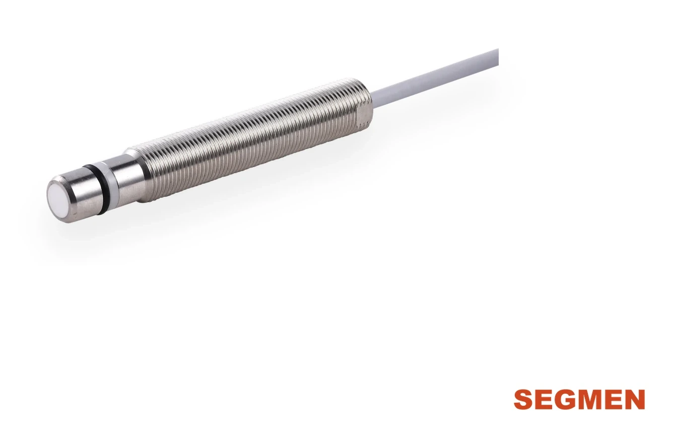
Pressure-rated inductive sensors for end-position detection inside hydraulic cylinders and pumps. The ceramic sensing face sits directly in the pressurized oil, so no separate pressure housing is needed.
- Pressure rating
- up to 1000 bar
- Protection
- IP67 / IP69K
- Sensing face
- Ceramic
- Housings
- M8 · M12 · M18
Key facts
A SEGMENsensor high-pressure inductive proximity sensor detects a metal target through a ceramic sensing face that sits directly in pressurized hydraulic oil, typically to confirm piston end position in a cylinder. SGI-HP models in M8 and M12 are rated 500 bar, and the M18 hydraulic-cylinder type comes in grades up to 1000 bar.
- M8 and M12 models are rated 500 bar (7250 psi) and sealed to IP67 and IP69K.
- The M18 hydraulic-cylinder type is offered in 250, 350, 500, 800 and 1000 bar grades.
- Sensing distance is 1 mm (M8), 1.5 mm (M12) and 2 mm (M12×1.5), flush mounted.
- Supply is 10–30 V DC for NPN/PNP or 10–60 V DC for 2-wire, with a 1 kHz switching frequency.
- Housings are stainless steel; qualification samples are 1–5 pcs.
Watch: how inductive sensors work and how they are tested
Transcript
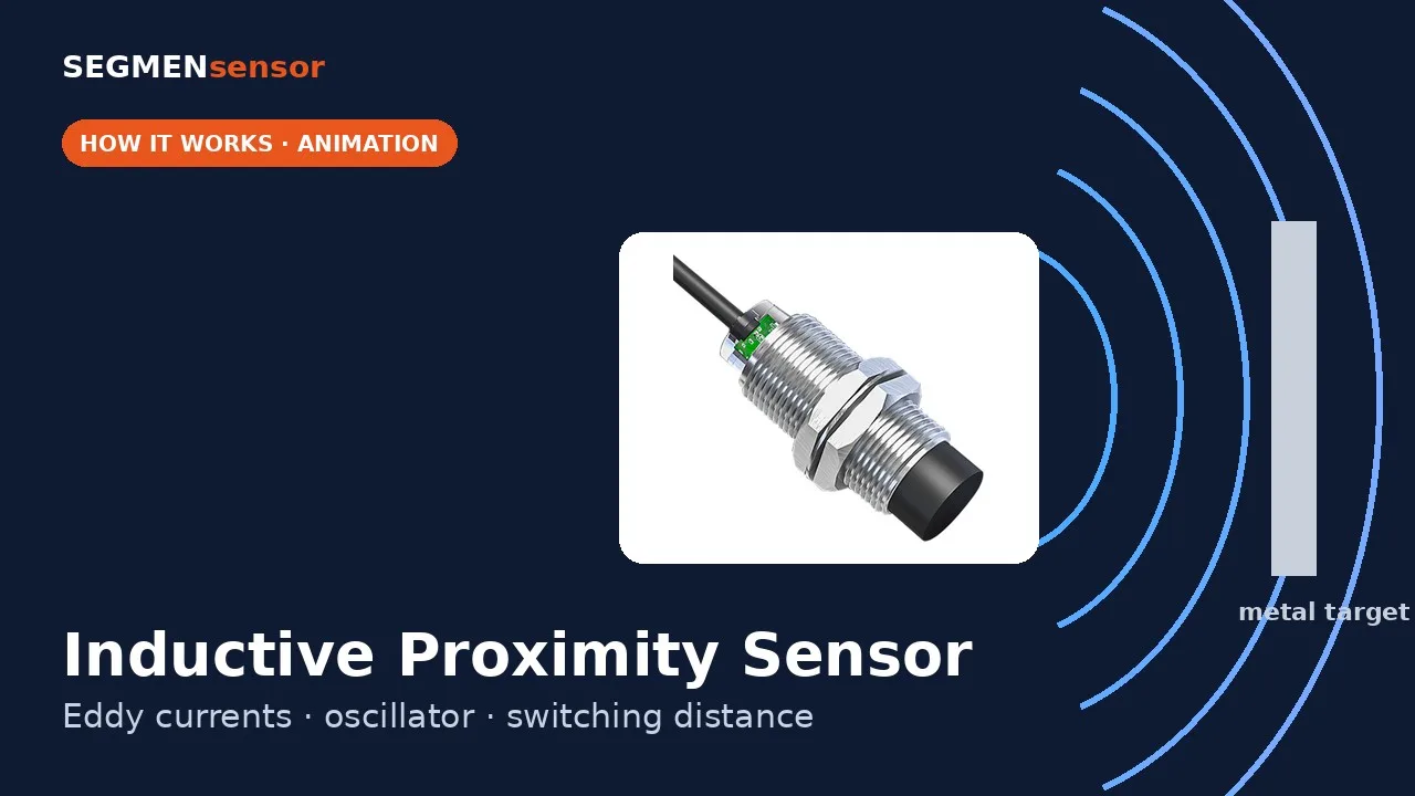
How does an inductive sensor detect metal without contact? Inside the sensor, an oscillator drives a coil wound on a ferrite core. It creates a high-frequency magnetic field in front of the sensing face. When a metal target enters the field, eddy currents are induced in the metal. They draw energy from the field, and the oscillation amplitude drops. When the amplitude falls below the threshold, the trigger switches the output, and the LED lights up. The switching distance, Sn, depends on the sensor size and the target material. Mild steel gives the full rated distance. SEGMENsensor inductive sensors: M8 to M30, Sn 1–25 mm. Learn more at segmensensor.com.
Transcript
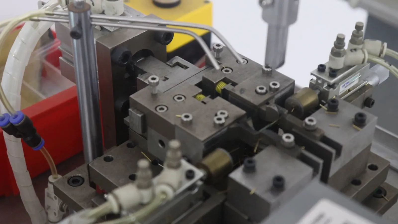
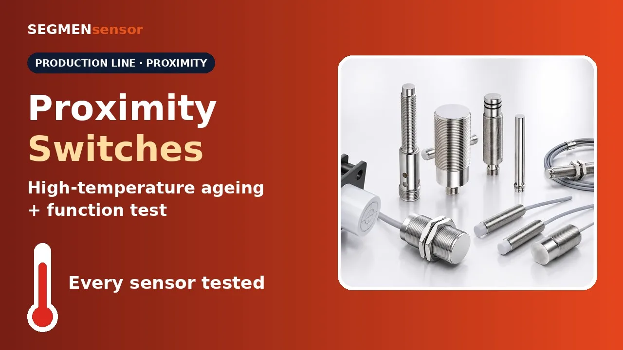
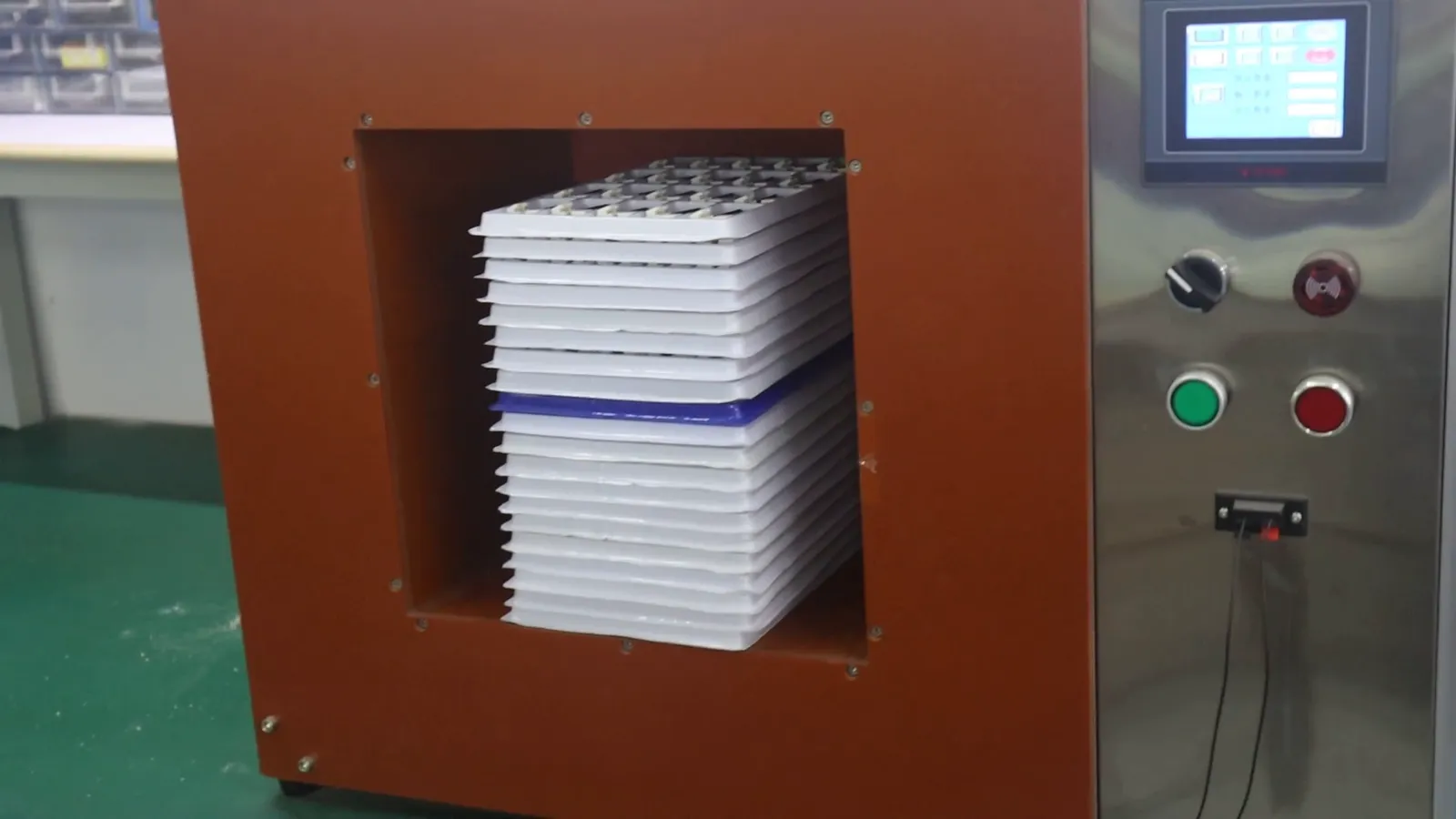
Proximity switches on the production line, from sensing element to final test. Reed sensing elements are fed into automatic assembly machines. Each element is positioned, formed and fitted automatically, one after another. Finished switches are aged in a high-temperature test chamber. Dedicated test stations then check the switching function and the output of every sensor. The readings on each station are checked before the sensors are packed. Every sensor tested · OEM volume supply. Request a quote at segmensensor.com.
Quick answer
What is a high-pressure inductive proximity sensor?
A high-pressure inductive proximity sensor detects a metal target through a pressure-resistant sensing face, which is why it is also called a pressure resistant inductive sensor. SEGMENsensor HP models in M8 and M12 are rated to 500 bar (7250 psi) and sealed to IP67 and IP69K. The M18 hydraulic-cylinder type comes in pressure grades up to 1000 bar. Both work as a hydraulic cylinder position sensor, reporting piston end position from inside the cylinder. For leak-tight installation, read sealing the mounting hole of a high-pressure proximity sensor.
Model finder
Choose by housing, output and connection
M8 and M12 models in the table are rated to 500 bar. For up to 1000 bar, see the M18 hydraulic-cylinder type below the table. Housing length is the last part of the part number.
| Part number | Housing | Length | Sensing distance | Output | Supply | Connection | |
|---|---|---|---|---|---|---|---|
| SGI-HP08S-010NA-C2-L28 | M8 | 28 mm | 1.0 mm | NPN NO | 10–30 VDC | 2 m cable | Quote |
| SGI-HP08S-010NB-C2-L28 | M8 | 28 mm | 1.0 mm | NPN NC | 10–30 VDC | 2 m cable | Quote |
| SGI-HP08S-010PA-C2-L28 | M8 | 28 mm | 1.0 mm | PNP NO | 10–30 VDC | 2 m cable | Quote |
| SGI-HP08S-010PB-C2-L28 | M8 | 28 mm | 1.0 mm | PNP NC | 10–30 VDC | 2 m cable | Quote |
| SGI-HP12S-015DA-C2-L43 | M12 | 43 mm | 1.5 mm | DC 2-wire NO | 10–60 VDC | 2 m cable | Quote |
| SGI-HP12S-015DB-C2-L43 | M12 | 43 mm | 1.5 mm | DC 2-wire NC | 10–60 VDC | 2 m cable | Quote |
| SGI-HP12S-015NA-C2-L43 | M12 | 43 mm | 1.5 mm | NPN NO | 10–30 VDC | 2 m cable | Quote |
| SGI-HP12S-015NB-C2-L43 | M12 | 43 mm | 1.5 mm | NPN NC | 10–30 VDC | 2 m cable | Quote |
| SGI-HP12S-015PA-C2-L43 | M12 | 43 mm | 1.5 mm | PNP NO | 10–30 VDC | 2 m cable | Quote |
| SGI-HP12S-015PB-C2-L43 | M12 | 43 mm | 1.5 mm | PNP NC | 10–30 VDC | 2 m cable | Quote |
| SGI-HP12S-015DA-C2-L47 | M12 | 47 mm | 1.5 mm | DC 2-wire NO | 10–60 VDC | 2 m cable | Quote |
| SGI-HP12S-015DB-C2-L47 | M12 | 47 mm | 1.5 mm | DC 2-wire NC | 10–60 VDC | 2 m cable | Quote |
| SGI-HP12S-015NA-C2-L47 | M12 | 47 mm | 1.5 mm | NPN NO | 10–30 VDC | 2 m cable | Quote |
| SGI-HP12S-015NB-C2-L47 | M12 | 47 mm | 1.5 mm | NPN NC | 10–30 VDC | 2 m cable | Quote |
| SGI-HP12S-015PA-C2-L47 | M12 | 47 mm | 1.5 mm | PNP NO | 10–30 VDC | 2 m cable | Quote |
| SGI-HP12S-015PB-C2-L47 | M12 | 47 mm | 1.5 mm | PNP NC | 10–30 VDC | 2 m cable | Quote |
| SGI-HP12S-015DA-C2-L50 | M12 | 50 mm | 1.5 mm | DC 2-wire NO | 10–60 VDC | 2 m cable | Quote |
| SGI-HP12S-015DB-C2-L50 | M12 | 50 mm | 1.5 mm | DC 2-wire NC | 10–60 VDC | 2 m cable | Quote |
| SGI-HP12S-015NA-C2-L50 | M12 | 50 mm | 1.5 mm | NPN NO | 10–30 VDC | 2 m cable | Quote |
| SGI-HP12S-015NB-C2-L50 | M12 | 50 mm | 1.5 mm | NPN NC | 10–30 VDC | 2 m cable | Quote |
| SGI-HP12S-015PA-C2-L50 | M12 | 50 mm | 1.5 mm | PNP NO | 10–30 VDC | 2 m cable | Quote |
| SGI-HP12S-015PB-C2-L50 | M12 | 50 mm | 1.5 mm | PNP NC | 10–30 VDC | 2 m cable | Quote |
| SGI-HP12S-015DA-C2-L55 | M12 | 55 mm | 1.5 mm | DC 2-wire NO | 10–60 VDC | 2 m cable | Quote |
| SGI-HP12S-015DB-C2-L55 | M12 | 55 mm | 1.5 mm | DC 2-wire NC | 10–60 VDC | 2 m cable | Quote |
| SGI-HP12S-015NA-C2-L55 | M12 | 55 mm | 1.5 mm | NPN NO | 10–30 VDC | 2 m cable | Quote |
| SGI-HP12S-015NB-C2-L55 | M12 | 55 mm | 1.5 mm | NPN NC | 10–30 VDC | 2 m cable | Quote |
| SGI-HP12S-015PA-C2-L55 | M12 | 55 mm | 1.5 mm | PNP NO | 10–30 VDC | 2 m cable | Quote |
| SGI-HP12S-015PB-C2-L55 | M12 | 55 mm | 1.5 mm | PNP NC | 10–30 VDC | 2 m cable | Quote |
| SGI-HP12S-015DA-C2-L56 | M12 | 56 mm | 1.5 mm | DC 2-wire NO | 10–60 VDC | 2 m cable | Quote |
| SGI-HP12S-015DA-Q4-L56 | M12 | 56 mm | 1.5 mm | DC 2-wire NO | 10–60 VDC | M12 connector | Quote |
| SGI-HP12S-015DB-C2-L56 | M12 | 56 mm | 1.5 mm | DC 2-wire NC | 10–60 VDC | 2 m cable | Quote |
| SGI-HP12S-015DB-Q4-L56 | M12 | 56 mm | 1.5 mm | DC 2-wire NC | 10–60 VDC | M12 connector | Quote |
| SGI-HP12S-015NA-C2-L56 | M12 | 56 mm | 1.5 mm | NPN NO | 10–30 VDC | 2 m cable | Quote |
| SGI-HP12S-015NA-Q4-L56 | M12 | 56 mm | 1.5 mm | NPN NO | 10–30 VDC | M12 connector | Quote |
| SGI-HP12S-015NB-C2-L56 | M12 | 56 mm | 1.5 mm | NPN NC | 10–30 VDC | 2 m cable | Quote |
| SGI-HP12S-015NB-Q4-L56 | M12 | 56 mm | 1.5 mm | NPN NC | 10–30 VDC | M12 connector | Quote |
| SGI-HP12S-015PA-C2-L56 | M12 | 56 mm | 1.5 mm | PNP NO | 10–30 VDC | 2 m cable | Quote |
| SGI-HP12S-015PA-Q4-L56 | M12 | 56 mm | 1.5 mm | PNP NO | 10–30 VDC | M12 connector | Quote |
| SGI-HP12S-015PB-C2-L56 | M12 | 56 mm | 1.5 mm | PNP NC | 10–30 VDC | 2 m cable | Quote |
| SGI-HP12S-015PB-Q4-L56 | M12 | 56 mm | 1.5 mm | PNP NC | 10–30 VDC | M12 connector | Quote |
| SGI-HP12S-015DA-Q4-L69 | M12 | 69 mm | 1.5 mm | DC 2-wire NO | 10–60 VDC | M12 connector | Quote |
| SGI-HP12S-015DB-Q4-L69 | M12 | 69 mm | 1.5 mm | DC 2-wire NC | 10–60 VDC | M12 connector | Quote |
| SGI-HP12S-015NA-Q4-L69 | M12 | 69 mm | 1.5 mm | NPN NO | 10–30 VDC | M12 connector | Quote |
| SGI-HP12S-015NB-Q4-L69 | M12 | 69 mm | 1.5 mm | NPN NC | 10–30 VDC | M12 connector | Quote |
| SGI-HP12S-015PA-Q4-L69 | M12 | 69 mm | 1.5 mm | PNP NO | 10–30 VDC | M12 connector | Quote |
| SGI-HP12S-015PB-Q4-L69 | M12 | 69 mm | 1.5 mm | PNP NC | 10–30 VDC | M12 connector | Quote |
| SGI-HP12S-015DA-C2-L78 | M12 | 78 mm | 1.5 mm | DC 2-wire NO | 10–60 VDC | 2 m cable | Quote |
| SGI-HP12S-015DA-Q4-L78 | M12 | 78 mm | 1.5 mm | DC 2-wire NO | 10–60 VDC | M12 connector | Quote |
| SGI-HP12S-015DB-C2-L78 | M12 | 78 mm | 1.5 mm | DC 2-wire NC | 10–60 VDC | 2 m cable | Quote |
| SGI-HP12S-015DB-Q4-L78 | M12 | 78 mm | 1.5 mm | DC 2-wire NC | 10–60 VDC | M12 connector | Quote |
| SGI-HP12S-015NA-C2-L78 | M12 | 78 mm | 1.5 mm | NPN NO | 10–30 VDC | 2 m cable | Quote |
| SGI-HP12S-015NA-Q4-L78 | M12 | 78 mm | 1.5 mm | NPN NO | 10–30 VDC | M12 connector | Quote |
| SGI-HP12S-015NB-C2-L78 | M12 | 78 mm | 1.5 mm | NPN NC | 10–30 VDC | 2 m cable | Quote |
| SGI-HP12S-015NB-Q4-L78 | M12 | 78 mm | 1.5 mm | NPN NC | 10–30 VDC | M12 connector | Quote |
| SGI-HP12S-015PA-C2-L78 | M12 | 78 mm | 1.5 mm | PNP NO | 10–30 VDC | 2 m cable | Quote |
| SGI-HP12S-015PA-Q4-L78 | M12 | 78 mm | 1.5 mm | PNP NO | 10–30 VDC | M12 connector | Quote |
| SGI-HP12S-015PB-C2-L78 | M12 | 78 mm | 1.5 mm | PNP NC | 10–30 VDC | 2 m cable | Quote |
| SGI-HP12S-015PB-Q4-L78 | M12 | 78 mm | 1.5 mm | PNP NC | 10–30 VDC | M12 connector | Quote |
| SGI-HP12S-015DA-Q4-L94 | M12 | 94 mm | 1.5 mm | DC 2-wire NO | 10–60 VDC | M12 connector | Quote |
| SGI-HP12S-015DB-Q4-L94 | M12 | 94 mm | 1.5 mm | DC 2-wire NC | 10–60 VDC | M12 connector | Quote |
| SGI-HP12S-015NA-Q4-L94 | M12 | 94 mm | 1.5 mm | NPN NO | 10–30 VDC | M12 connector | Quote |
| SGI-HP12S-015NB-Q4-L94 | M12 | 94 mm | 1.5 mm | NPN NC | 10–30 VDC | M12 connector | Quote |
| SGI-HP12S-015PA-Q4-L94 | M12 | 94 mm | 1.5 mm | PNP NO | 10–30 VDC | M12 connector | Quote |
| SGI-HP12S-015PB-Q4-L94 | M12 | 94 mm | 1.5 mm | PNP NC | 10–30 VDC | M12 connector | Quote |
| SGI-HP12S-015DA-Q4-L138 | M12 | 138 mm | 1.5 mm | DC 2-wire NO | 10–60 VDC | M12 connector | Quote |
| SGI-HP12S-015DB-Q4-L138 | M12 | 138 mm | 1.5 mm | DC 2-wire NC | 10–60 VDC | M12 connector | Quote |
| SGI-HP12S-015NA-Q4-L138 | M12 | 138 mm | 1.5 mm | NPN NO | 10–30 VDC | M12 connector | Quote |
| SGI-HP12S-015NB-Q4-L138 | M12 | 138 mm | 1.5 mm | NPN NC | 10–30 VDC | M12 connector | Quote |
| SGI-HP12S-015PA-Q4-L138 | M12 | 138 mm | 1.5 mm | PNP NO | 10–30 VDC | M12 connector | Quote |
| SGI-HP12S-015PB-Q4-L138 | M12 | 138 mm | 1.5 mm | PNP NC | 10–30 VDC | M12 connector | Quote |
| SGI-HP12FS-020DA-Q4 | M12×1.5 | — | 2.0 mm | DC 2-wire NO | 10–60 VDC | M12 connector | Quote |
| SGI-HP12FS-020DB-Q4 | M12×1.5 | — | 2.0 mm | DC 2-wire NC | 10–60 VDC | M12 connector | Quote |
| SGI-HP12FS-020NA-Q4 | M12×1.5 | — | 2.0 mm | NPN NO | 10–30 VDC | M12 connector | Quote |
| SGI-HP12FS-020NB-Q4 | M12×1.5 | — | 2.0 mm | NPN NC | 10–30 VDC | M12 connector | Quote |
| SGI-HP12FS-020PA-Q4 | M12×1.5 | — | 2.0 mm | PNP NO | 10–30 VDC | M12 connector | Quote |
| SGI-HP12FS-020PB-Q4 | M12×1.5 | — | 2.0 mm | PNP NC | 10–30 VDC | M12 connector | Quote |
M8 / M12 models: operating temperature -25 °C to +70 °C, flush mounting. M12×1.5 connector models (12F) have no length code in the part number.
M18 high-pressure inductive sensor for hydraulic cylinders
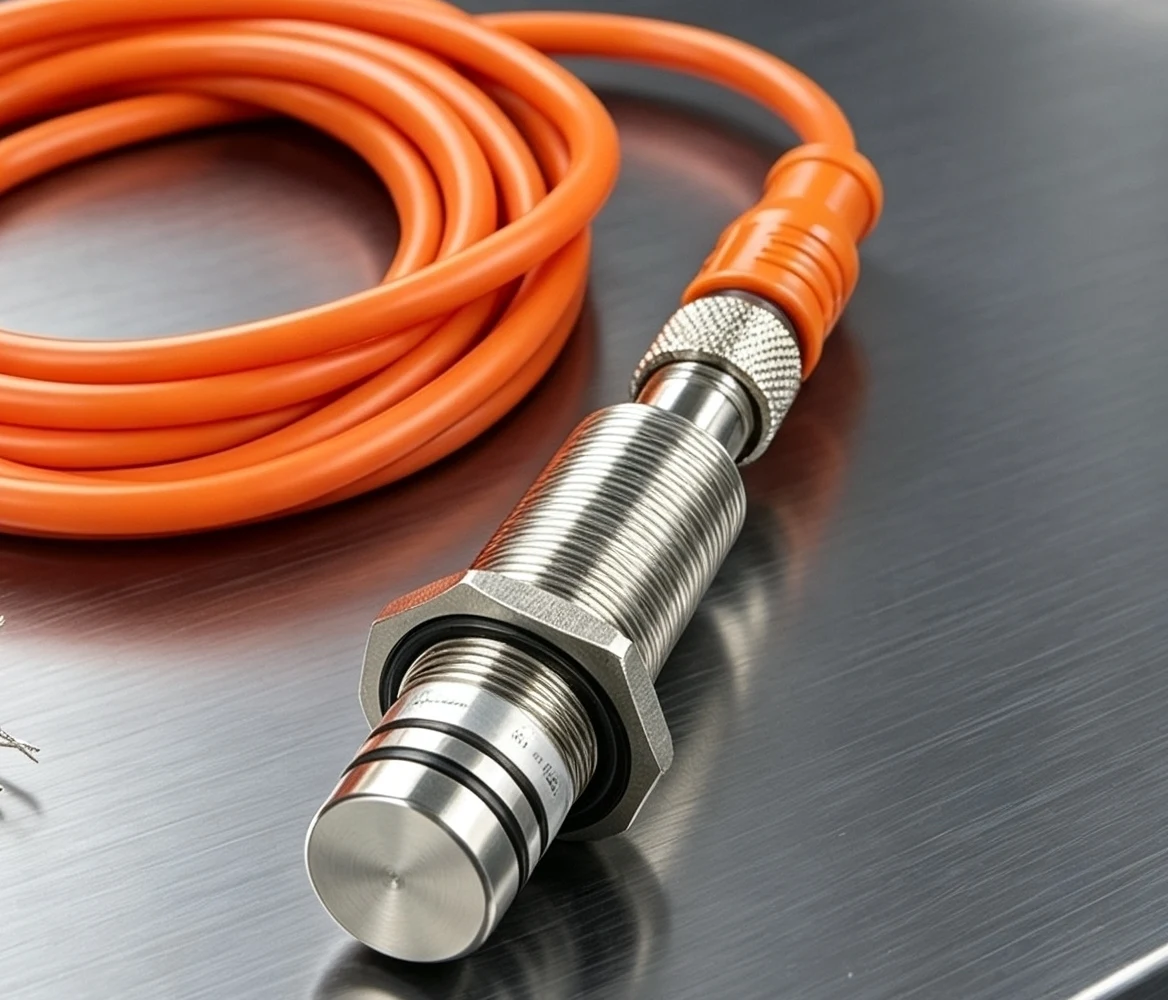
Order by pressure grade. Other M18 data is available on request.
Part number guide
Reading a SEGMENsensor part number
Typical application
End-position detection in hydraulic cylinders
- The sensor threads into the cylinder end cap with its ceramic face exposed to the oil.
- When the piston reaches end of stroke, it enters the sensing range.
- The output switches and the controller stops or reverses the stroke. No external cams or limit switches are needed.
Specifications
Technical data, M8 / M12 models
| Pressure rating | 500 bar (7250 psi) |
| Sensing distance | 1 mm (M8), 1.5 mm (M12), 2 mm (M12×1.5) |
| Mounting | Flush |
| Supply voltage | 10–30 VDC (NPN/PNP), 10–60 VDC (DC 2-wire) |
| Max. load current | 200 mA |
| No-load current | < 5 mA |
| Voltage drop | < 1.5 V |
| Switching frequency | 1 kHz |
| Hysteresis / repeatability | < 15 % Sr / < 1.0 % Sr |
| Operating temperature | -25 °C to +70 °C |
| Protection | IP67, IP69K |
| Protection circuits | Short-circuit, reverse polarity, overload (220 mA) |
| Housing / sensing face | Stainless steel / ceramic |
| Connection | 2 m oil-resistant PVC cable or M12 connector |
| LED indicator | Yes |
| Approvals | CE, RoHS |
Download the one-page datasheet (PDF)
The PDF covers the inductive proximity sensor range; the CSV lists every part number with its specification. More files: proximity sensor downloads. Dimension drawings are sent by email on request.
Standards: IEC 60947-5-2 (proximity switches) · IEC 60529 IP ratings
Comparison
HP series vs. a standard inductive sensor
| Feature | Standard inductive | SEGMENsensor HP |
|---|---|---|
| Pressure at sensing face | Not pressure-rated | 500 bar (M8/M12), up to 1000 bar (M18) |
| Sensing face | Plastic cap | Ceramic |
| Washdown rating | Usually IP67 | IP67 + IP69K |
| Mounting in cylinder | Outside, with cam or flag | Through the end cap |
“Standard inductive” describes a typical general-purpose sensor, not a specific product.
Ordering
Samples, MOQ and OEM
OEM volume supply. Sample and production lead times are confirmed with your quotation.
Contact us about OEM and private-label options.
Key specifications & options
SGI-HP key specifications, with bar / psi / MPa conversions
One line per item, taken from the specification table and the M18 card above. Pressure conversions are calculated values (1 bar = 14.5038 psi = 0.1 MPa), rounded.
- Pressure rating, M8 / M12: 500 bar ≈ 7,250 psi ≈ 50 MPa at the sensing face.
- Pressure grades, M18 hydraulic-cylinder type: 250 bar (≈ 3,600 psi, 25 MPa) · 350 bar (≈ 5,100 psi, 35 MPa) · 500 bar (≈ 7,250 psi, 50 MPa) · 800 bar (≈ 11,600 psi, 80 MPa) · 1000 bar (≈ 14,500 psi, 100 MPa).
- Sensing distance: 1 mm (M8), 1.5 mm (M12), 2 mm (M12×1.5 and M18), flush mounting.
- Output and supply: NPN or PNP 3-wire at 10–30 VDC, DC 2-wire at 10–60 VDC, normally open or normally closed (M18: NPN NO or PNP NO).
- Electrical, M8 / M12: max. load current 200 mA, no-load current < 5 mA, voltage drop < 1.5 V, switching frequency 1 kHz.
- Housing and connection: stainless steel with ceramic face; M12 lengths 43–138 mm; 2 m oil-resistant PVC cable or M12 connector (M18: orange PUR cable with detachable M12 plug).
- Protection, temperature and approvals: IP67 and IP69K; -25 °C to +70 °C (M8 / M12); CE, RoHS.
Bench-test an SGI-HP sensor on your own end cap first
Send the part number from the model finder, or your pressure, housing and output. We build 1–5 qualification samples in 5–7 working days, so you can check thread fit, sealing and switching point on your cylinder before an OEM order. Every inquiry gets an engineering reply within 24 hours.
Bench test and troubleshooting
How do you test a high-pressure proximity sensor before it goes into the cylinder?
Test it on the bench at atmospheric pressure, then again in the assembled cylinder: confirm wiring and switching point with a steel target, check the electrical values against the datasheet, and only then pressure-test the cylinder within the sensor's rating. Six steps:
- Inspect the sensor. Check the thread, the ceramic face and the O-rings (two on the M18 sensing head) for damage, and confirm the part number matches your drawing: housing, length code and output letters.
- Wire it on the bench. Use a 24 VDC supply: brown to +V, blue to 0 V; on NPN/PNP models the black wire goes to the PLC input or a test lamp. Wiring by output type: NPN vs PNP proximity sensor wiring.
- Find the switching point. Move a mild steel target toward the face. IEC 60947-5-2 uses a square Fe 360 steel plate, 1 mm thick, as the standard target. The LED and the PLC input should switch at or inside the rated sensing distance: 1 mm (M8), 1.5 mm (M12), 2 mm (M12×1.5, M18).
- Check the electrical values. With no load, current draw should stay below 5 mA; with the load connected, the voltage drop across the sensor should stay below 1.5 V and the load current at or below 200 mA.
- Set the working gap in the end cap. Work out where the piston stops relative to the sensing face and keep the gap within the assured operating distance, about 81% of Sn. Example: an M12 model with 1.5 mm Sn gives a working gap of about 1.2 mm or less (calculated value). How end-cap geometry sets this gap: end-of-stroke detection guide.
- Pressure-test the assembled cylinder, then repeat the switch check. Stay within the sensor rating (500 bar for M8 / M12, the ordered grade for M18), check the mounting thread for seepage, and run the end-of-stroke check again with the oil at working temperature (up to +70 °C for M8 / M12).
| Symptom | Likely cause | What to do |
|---|---|---|
| Output never switches, LED stays off | Supply or wiring fault, or the target never enters the sensing range | Check brown +V / blue 0 V at 10–30 VDC (NPN/PNP) or 10–60 VDC (DC 2-wire); bring a steel target inside the rated sensing distance |
| LED switches but the PLC input does not | Output type does not match the input: PNP needs a sinking input, NPN needs a sourcing input | Order the matching output (letter P or N in the part number) or change the input card setting |
| Output is on with no target | Normally closed version, or metal chips or burrs inside the sensing range | Check the contact letter (A = NO, B = NC); clean chips and burrs out of the bore |
| Output flickers at end of stroke | Working gap too close to Sn; the piston stops at the edge of the range | Reduce the gap to about 81% of Sn or less, for example about 1.2 mm on a 1.5 mm M12 model (calculated value) |
| Output drops out when the load is connected | Load current above 200 mA trips the short-circuit / overload protection | Keep the load at 200 mA or less; switch solenoids or lamps through a relay |
| DC 2-wire model never turns off at the PLC | The input does not accept the off-state current or the voltage drop (< 1.5 V) of a 2-wire sensor | Check that the input is rated for 2-wire sensors, or use a 3-wire NPN/PNP model |
| Oil seeps at the mounting thread after the pressure test | Damaged O-ring, wrong seal seat or poor bore finish | Replace the O-ring and check the bore against the drawing: mounting hole and sealing guide |
Selecting between pressure and temperature ratings for hot hydraulic oil: hydraulic cylinder proximity sensors for high pressure and hot oil. For continuous piston position instead of end-of-stroke switching, see the in-cylinder magnetostrictive position sensor.
Installation
How do you install a high-pressure proximity sensor in a cylinder end cap?
Machine the bore to the sensor drawing, seal on the seat or O-rings, set the gap within about 81% of Sn, wire and check the output, then pressure-test the cylinder before it leaves your line. Six steps:
- Match the pressure grade. Compare the maximum system pressure, including pressure peaks, with the rating: 500 bar (about 7,250 psi) for M8 and M12 SGI-HP models, 250, 350, 500, 800 or 1000 bar grades for the M18 hydraulic-cylinder type.
- Machine the bore to the drawing. Cut the thread, seal seat and bore depth to the sensor drawing so the ceramic face ends flush with the inner wall; chamfer and deburr the thread entry. Dimensions and drawing: mounting-hole and sealing guide.
- Seal on the seat or O-rings. Fit undamaged O-rings (the M18 type has two on the sensing head). Do not use thread tape or paste; the seal is made on the seat, not on the thread.
- Tighten to the specified torque. Use the torque on the datasheet or drawing, then confirm that the sensing face is flush and not recessed or protruding.
- Set the gap and wire. Keep the piston-to-face gap within the assured operating distance, about 81% of Sn (Sn = 1 mm M8, 1.5 mm M12, 2 mm M12×1.5 and M18). Wire at 24 VDC: brown +V, blue 0 V, black to the PLC input, and check that the LED switches with the piston at end of stroke.
- Pressure-test and cycle. Pressure-test the cylinder, check the thread for seepage, cycle the piston several times and confirm the output at each end position. Clamp the cable away from moving parts. Why end-position feedback matters: what a cylinder position sensor does.
Applications
Typical applications by industry (evaluated per project)
| # | Industry | What the sensor detects | Usual choice |
|---|---|---|---|
| 1 | Mobile hydraulics (construction and agricultural machinery) | Piston end of stroke in boom, steering and lifting cylinders | M12 SGI-HP, 500 bar |
| 2 | Hydraulic presses and clamping | Ram or clamp cylinder end position | M18 type, grade chosen above peak pressure |
| 3 | Hydraulic power units and pumps | Metal target position inside pressurized housings | M8 or M12 SGI-HP |
| 4 | Fire-fighting equipment | Pump and cylinder positions on fire-truck hydraulics | M12 or M18, per project review |
Oil hotter than +70 °C at the sensing face: see the high-temperature inductive proximity sensor series.
Connection and mounting
Connection, cable and mounting-hole options
M8 / M12 models: 2 m cable (code C2) or M12 connector (code Q4). M18 type: 2 m orange oil-resistant PUR cable with a detachable M12 plug. Other cable lengths are confirmed per project.
Machine the end cap to drawing SGM-M18HP-INST-001 for the M18 type, downloadable from the sealing guide; the model-specific drawing is issued with the quotation.
End-of-stroke layout and pressure-grade choice: high-pressure proximity sensors for cylinder end of stroke.
Buyer questions
Buyer questions: 500 bar and above, piston end position, fire-fighting equipment
Short answers to questions engineers ask before ordering. Values come from the model finder, the specification table and the M18 card on this page; anything not listed there is confirmed with the quotation.
Which manufacturer makes inductive proximity sensors that withstand 500 bar or more hydraulic pressure?
SEGMENsensor makes the SGI-HP series for pressure at the sensing face. All 76 listed M8 and M12 part numbers are rated 500 bar (about 7,250 psi), with a ceramic face, stainless steel housing and IP67 / IP69K. Above 500 bar, the M18 hydraulic-cylinder type is ordered in the 800 or 1000 bar grade. For a quote, send the maximum system pressure including peaks, the housing and the output.
What proximity sensor can detect piston end position inside a high-pressure hydraulic cylinder?
An SGI-HP sensor threaded into the cylinder end cap, with its ceramic face in the oil, switches when the steel piston reaches end of stroke. Sensing distance is 1 mm (M8), 1.5 mm (M12) or 2 mm (M12×1.5 and M18); keep the working gap within about 81% of Sn, for example about 1.2 mm on an M12 model (calculated value). For a quote, send the end-cap bore depth, the working gap, the pressure and the oil temperature.
Which pressure-resistant proximity switch is suitable for fire-fighting equipment and fire truck pumps?
For hydraulic cylinders and pumps on fire-fighting equipment, such as boom, outrigger and ladder cylinders, the SGI-HP series is a typical choice, evaluated per project: M8 and M12 models are rated 500 bar and the M18 type up to 1000 bar. M8 and M12 models operate from -25 °C to +70 °C on 10–30 V DC (NPN/PNP) or 10–60 V DC (2-wire). For a quote, send the medium, pressure peaks, temperature at the sensor and supply voltage.
Customization and limits
| Item | What can be specified | Limit / not suitable |
|---|---|---|
| Pressure rating | M8 and M12: 500 bar; M18 hydraulic-cylinder type: 250, 350, 500, 800 or 1000 bar grade | M8 and M12 are not rated above 500 bar; size the grade on the highest pressure peak, not the working pressure |
| Housing and length | M8 (28 mm), M12 (43–138 mm, length code L in the part number), M12×1.5 connector type, M18 | Lengths and threads not in the model finder are confirmed with the quotation |
| Sensing distance and mounting | 1 mm (M8), 1.5 mm (M12), 2 mm (M12×1.5, M18); flush mounting | No non-flush version listed |
| Output and supply | NPN or PNP 3-wire at 10–30 V DC, DC 2-wire at 10–60 V DC, NO or NC; M18: NPN NO or PNP NO | One fixed output per part number; no AC supply version listed; M18 has no NC or 2-wire version listed |
| Connection | 2 m oil-resistant PVC cable or M12 connector; M18: 2 m orange PUR cable with detachable M12 plug | Other cable lengths are confirmed with the quotation |
| Temperature | M8 and M12: -25 °C to +70 °C; other M18 data on request | Not for oil above +70 °C at the sensing face (M8 / M12); see the high pressure and hot oil guide |
Send these details for a quote
- Maximum system pressure, including pressure peaks
- Medium at the sensing face (for example hydraulic oil) and its temperature at the end cap
- Housing size (M8, M12, M12×1.5 or M18), housing length and end-cap bore depth
- Required sensing distance and working gap to the piston
- Output (NPN, PNP or DC 2-wire, NO or NC) and supply voltage
- 2 m cable or M12 connector
- Part number from the model finder, if known
- Quantity: qualification samples (1–5 pcs, 5–7 working days) and estimated annual volume
- Application, for example hydraulic cylinder end position, hydraulic pump or fire-fighting equipment
Sourcing for an OEM program? See the inductive proximity sensor OEM guide.
FAQ
Common questions
What pressure can an inductive proximity sensor withstand?
A standard inductive sensor is not rated for pressure at the sensing face. SEGMENsensor M8 and M12 HP models are rated to 500 bar (7250 psi). The M18 hydraulic-cylinder type is available in grades of 250, 350, 500, 800 and 1000 bar.
Where is the sensor installed in a hydraulic cylinder?
It threads into the end cap so the sensing face sits in the oil. When the piston reaches end of stroke it comes within the sensing range (1 to 2 mm depending on size) and the output switches.
Which housing length should I choose?
Pick the length that matches the depth of the mounting bore in your end cap. M12 models are available from 43 mm to 138 mm; the length is the last part of the part number, for example L69 for 69 mm.
Which model do I need for 1000 bar?
Choose the M18 hydraulic-cylinder type in the 1000 bar grade. M8 and M12 models are rated to 500 bar.
What is the operating temperature range?
M8 and M12 HP models operate from -25 °C to +70 °C. For hotter processes, see the SEGMENsensor high-temperature series.
Do you offer NPN, PNP and 2-wire versions?
Yes. NPN and PNP 3-wire models run on 10 to 30 VDC. DC 2-wire models run on 10 to 60 VDC. Each is available normally open or normally closed.
What does IP69K mean?
IP69K is a protection level for high-pressure, high-temperature washdown. It is defined in ISO 20653; IP67 comes from IEC 60529, the standard for enclosure protection.
How do I test a high-pressure proximity sensor before installing it in the cylinder?
Bench-test it at atmospheric pressure first. Power it at 24 VDC, connect brown to +V, blue to 0 V and black to the PLC input, then move a mild steel target toward the face and confirm that the LED and the PLC input switch at or inside the rated sensing distance (1 mm M8, 1.5 mm M12, 2 mm M12×1.5 and M18). Then check the thread and the O-ring seats before fitting the sensor to the end cap.
How many psi is 1000 bar?
1000 bar is about 14,500 psi or 100 MPa (1 bar = 14.5038 psi, calculated value). The SEGMENsensor M18 hydraulic-cylinder type is offered in 250, 350, 500, 800 and 1000 bar grades; M8 and M12 HP models are rated 500 bar (about 7,250 psi).
What should an RFQ for a high-pressure proximity sensor include?
State the maximum system pressure including pressure peaks, the housing (M8, M12 or M18) and housing length, the sensing distance, the output (NPN, PNP or DC 2-wire, NO or NC), cable or M12 connector, the oil temperature at the end cap and your annual volume. We reply within 24 hours and can ship 1–5 qualification samples in 5–7 working days.
What is the production lead time and MOQ for SGI-HP sensors?
Production lead time and MOQ are confirmed with the quotation, because they depend on the housing, pressure grade, output and order quantity. Standard qualification samples of 1–5 pcs ship in 5–7 working days; customized samples take 7–14 days. Every inquiry is answered within 24 hours.
Can SGI-HP sensors be customized for a specific hydraulic cylinder?
Yes. Options include the housing length (M12 from 43 mm to 138 mm), NPN, PNP or DC 2-wire output, normally open or normally closed, 2 m cable or M12 connector, cable length, and the M18 pressure grade from 250 to 1000 bar. Each OEM request is reviewed against your end-cap drawing and confirmed per project.
How are orders shipped, and what does the quotation include?
Quotations are FOB China. International freight, import duties and taxes are not included and are arranged by the buyer. Payment is 100% T/T in advance for all orders.
Can I test samples before placing a production order?
Yes. Order 1–5 qualification samples, bench-test them as described on this page, then fit them to your own end cap and pressure-test the cylinder. Samples ship in 5–7 working days. Give us the maximum system pressure, housing, length and output so the samples match the production version.
What warranty do SGI-HP high-pressure sensors carry?
SEGMENsensor high-pressure inductive proximity sensors carry a 12-month warranty. Production follows an ISO 9001:2015 quality management system.
Request qualification samples or an engineering review
Tell us the maximum system pressure, the housing and length, the sensing distance and the output. We reply within 24 hours and ship 1–5 qualification samples in 5–7 working days; production lead time and MOQ are confirmed with the quotation. Download the datasheet first if you need the full specification.