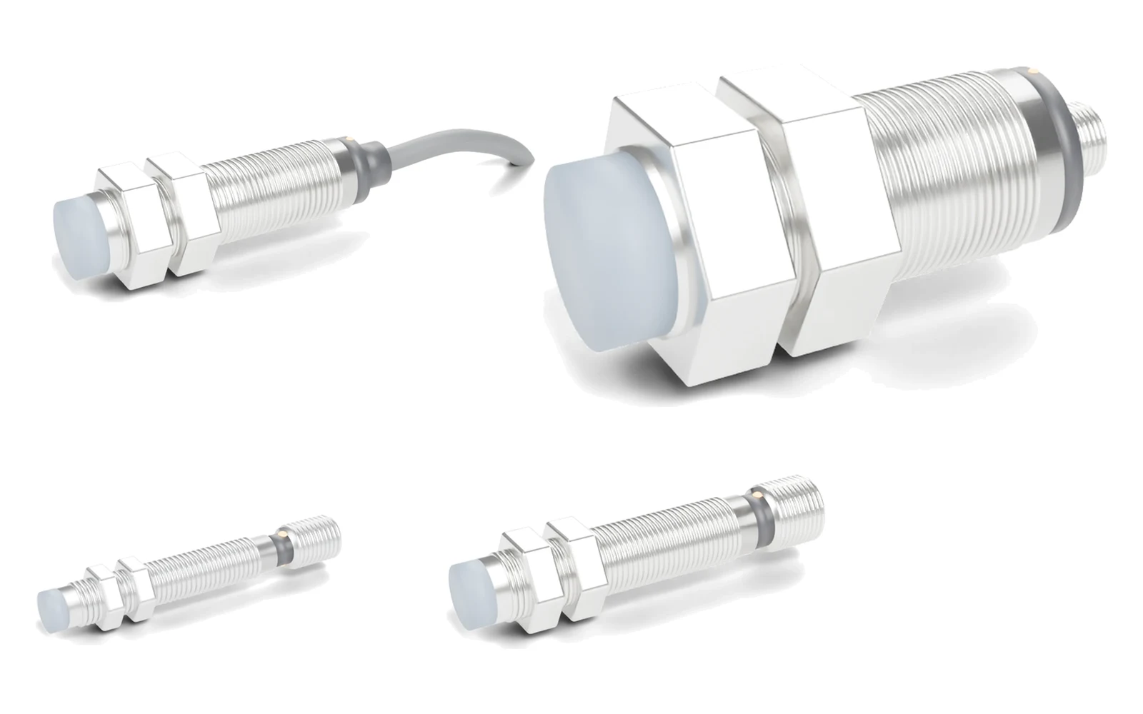
Hysteresis is the built-in gap between the switch-on and switch-off distances of a proximity sensor. It is deliberate: without it, a target vibrating at the switching point would toggle the output many times and a PLC would count false pulses. For design, place the target at or below 0.8 × Sn for the "on" position and beyond 1.32 × Sn for the "off" position, or use the hysteresis value on the datasheet of the part number.
How is proximity sensor hysteresis defined and measured?
Hysteresis (H) is measured by moving a standard target slowly towards the sensing face until the output switches (the switch-on distance, which is the real switching distance Sr), then moving it away until the output switches back (the switch-off distance). The difference is expressed relative to Sr:
H (%) = (soff − son) ÷ Sr × 100 → soff = Sr × (1 + H)
IEC 60947-5-2, the product standard for inductive and capacitive proximity switches, measures switching distances with a 1 mm thick mild steel (Fe 360) square target and limits the differential travel to 20% of Sr. The value on a datasheet is a maximum; individual sensors usually fall below it.

Why do proximity sensors need hysteresis?
Hysteresis prevents output chatter. Inside an inductive sensor, a Schmitt trigger compares the oscillator amplitude with two thresholds instead of one: the output switches on when the amplitude falls below the lower threshold and switches off only when it rises above the higher one. A target that stops exactly at the switching point, or vibrates there by a few hundredths of a millimetre, therefore produces one clean transition instead of a burst of pulses. The oscillator and trigger stages are explained step by step in how an inductive proximity sensor works.
Too much hysteresis has a cost: the target must travel further before the output resets, which matters on short strokes, small cams and end-of-stroke detection in hydraulic cylinders.
Is hysteresis the same as repeatability or switching distance tolerance?
No. Three different datasheet values describe where a proximity sensor switches, and they are often confused:
| Parameter | What it describes | IEC 60947-5-2 limit | SGI-HP (M8 / M12) |
|---|---|---|---|
| Hysteresis H | Gap between switch-on (approach) and switch-off (retreat) distances on one sensor | ≤ 20% of Sr | < 15% Sr |
| Repeat accuracy R | Scatter of the switch-on point when the same sensor is tested repeatedly under the same conditions | ≤ 10% of Sr | < 1.0% Sr |
| Real switching distance Sr | Where one individual sensor actually switches on, compared with the rated Sn | 90–110% of Sn | Sn = 1 mm (M8), 1.5 mm (M12) |
Repeatability tells you how consistently the sensor switches at the same point; hysteresis tells you how far the target must back off before it switches back. A sensor can have excellent repeatability and still a large hysteresis band. The relation between Sn, Sr and the assured distance is covered in the proximity sensor sensing distance guide.
How do you calculate the switch-off distance?
- Find Sr. Measure the switch-on distance on the sensor, or use the tolerance band 0.9–1.1 × Sn if you design for any unit.
- Take H from the datasheet. If none is published, use the IEC 60947-5-2 maximum of 20%.
- Calculate soff = Sr × (1 + H). This is the distance beyond which the output is guaranteed to switch off.
- Set the "off" position beyond the worst case and the "on" position inside the assured distance (about 0.8 × Sn or less).
Worked example 1 (calculated): an M12 SGI-HP high-pressure inductive sensor has Sn = 1.5 mm and hysteresis below 15% Sr. A sample that switches on at 1.50 mm switches off before 1.50 × 1.15 = 1.725 mm. Across all units, Sr can be up to 1.65 mm, so the worst-case switch-off distance is 1.65 × 1.15 ≈ 1.90 mm. Design the piston target to stop at 1.2 mm or less for "on" and to retreat beyond 1.9 mm for "off".
Worked example 2 (calculated): an M18 flush general-purpose sensor with Sn = 8 mm, sized with the IEC limits: "on" position ≤ 0.8 × 8 = 6.4 mm; "off" position ≥ 1.1 × 8 × 1.2 ≈ 10.6 mm. A cam whose lobe and base circle differ by less than about 4.2 mm cannot guarantee both states with this sensor.
Quick calculator: switch-on and switch-off positions
Enter the rated sensing distance and the hysteresis from the datasheet (20% if not stated).
"On" position ≤ 1.20 mm · worst-case switch-off 1.90 mm · place "off" position beyond 1.90 mm
For other unit and signal calculations, see the engineering calculators.
What problems does hysteresis cause, and how do you fix them?
| Symptom | Cause | Fix |
|---|---|---|
| Output flickers or switches late at end of stroke | Target stops between Sr and Sr × (1 + H) | Move the stop position to 0.8 × Sn or closer |
| Output stays on after the target has left | "Off" position is still inside the hysteresis band | Increase travel beyond 1.32 × Sn, or use a smaller Sn sensor mounted closer |
| Works on one machine, not on the next | Sr varies 90–110% of Sn between units | Design for the worst case, not for the sample on the bench |
| Double counts on a vibrating part | Vibration amplitude larger than the hysteresis band | Reduce vibration, move the switching point away from the rest position, or add a PLC input filter |
| Switches closer on aluminium or brass | Non-ferrous targets reduce Sr, and the band shifts with it | Apply the material factor before the hysteresis calculation |
For wiring and multimeter checks, use the proximity sensor not detecting troubleshooting guide. For fast targets, also check the switching frequency.
Do capacitive proximity sensors have hysteresis too?
Yes. IEC 60947-5-2 applies the same definition to capacitive proximity switches. On a capacitive sensor the switching point also depends on the target's dielectric constant and on the sensitivity setting where it is adjustable, so the hysteresis band moves whenever Sr moves. Check the switch-off point with the actual target material, for example the filled and empty level in a hopper. See inductive vs capacitive proximity sensors for the differences.
Which SEGMENsensor sensors publish a hysteresis value?
- SGI-HP high-pressure inductive sensors — M8 and M12, 500 bar, Sn 1–1.5 mm (2 mm M12×1.5): hysteresis < 15% Sr, repeatability < 1.0% Sr, 1 kHz. Used for piston end-position detection; see end-of-stroke detection in hydraulic cylinders.
- SGI-GP general-purpose inductive sensors — 6.5 mm to M30, flush or non-flush; the hysteresis of each part number is given on the datasheet sent with the quotation.
To identify a sensor already on your machine, use the proximity sensor part number lookup.
Short stroke or small cam?
Send the target travel between the "on" and "off" positions, the target material, the mounting (flush or non-flush) and the PLC input type. Our engineers will check the hysteresis margin and recommend a housing and series. Qualification samples 1–5 pcs in 5–7 working days · FOB China · reply within 24 hours.
Download the inductive proximity sensor datasheet (PDF)
Sensing distance, supply voltage, output types, switching frequency, housing and temperature data for the SEGMENsensor inductive proximity range. Size-specific datasheets are also available for M8, M12, M18 and M30, flush and non-flush. No registration required.
Frequently Asked Questions
The output switches off at a distance up to 15% larger than the distance where it switched on. If a sensor switches on at 1.50 mm, it switches off again before 1.50 × 1.15 = 1.725 mm (calculated). SEGMENsensor SGI-HP high-pressure sensors specify hysteresis below 15% Sr.
IEC 60947-5-2 limits the differential travel of a proximity switch to 20% of the real switching distance Sr. The standard also requires Sr to be within 90–110% of the rated distance Sn, so the worst-case switch-off distance is 1.1 × 1.2 = 1.32 × Sn (calculated).
No. Repeatability is the scatter of the switch-on point when the same sensor is tested repeatedly; hysteresis is the gap between switch-on and switch-off. IEC 60947-5-2 allows repeat accuracy up to 10% of Sr, and SGI-HP sensors specify below 1.0% Sr.
The target probably stops inside the hysteresis band, between Sr and Sr × (1 + H). Increase the travel so the off position is beyond 1.32 × Sn, or use a sensor with a smaller sensing distance mounted closer to the target.
On standard inductive sensors it is fixed by the trigger circuit. On capacitive sensors with a sensitivity adjustment, changing the setting moves Sr and the hysteresis band moves with it. Ask us for the datasheet value of a specific part number.
The distance between the on and off positions of the target, the target material and size, flush or non-flush mounting, temperature, pressure at the sensing face and the PLC input type. Our engineers reply within 24 hours.