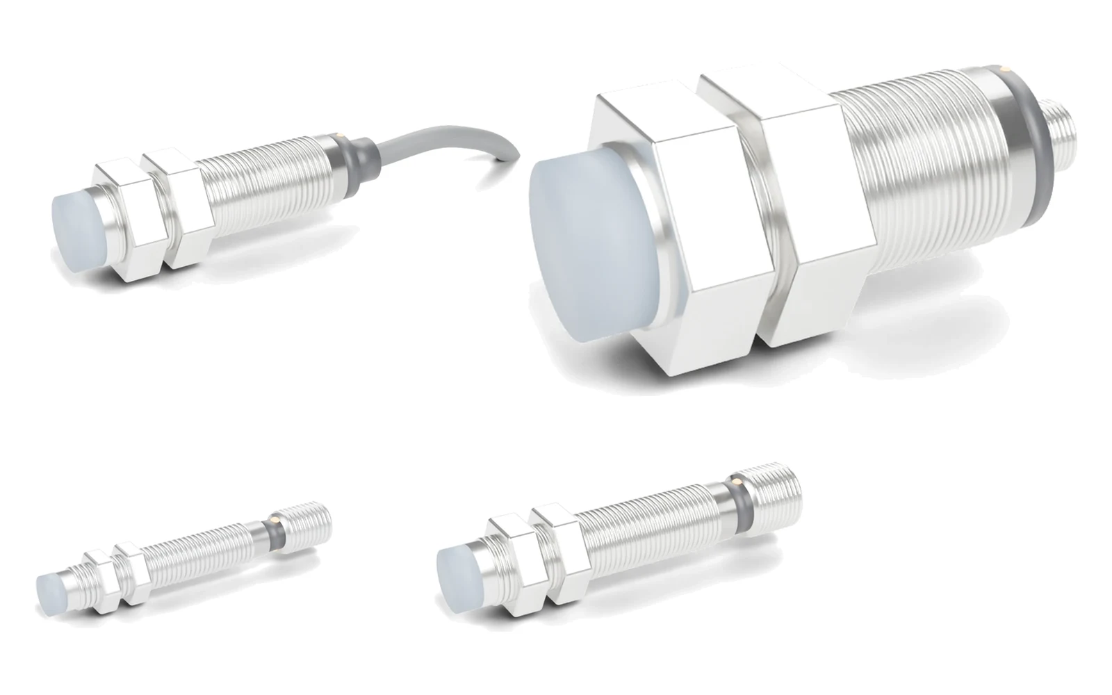
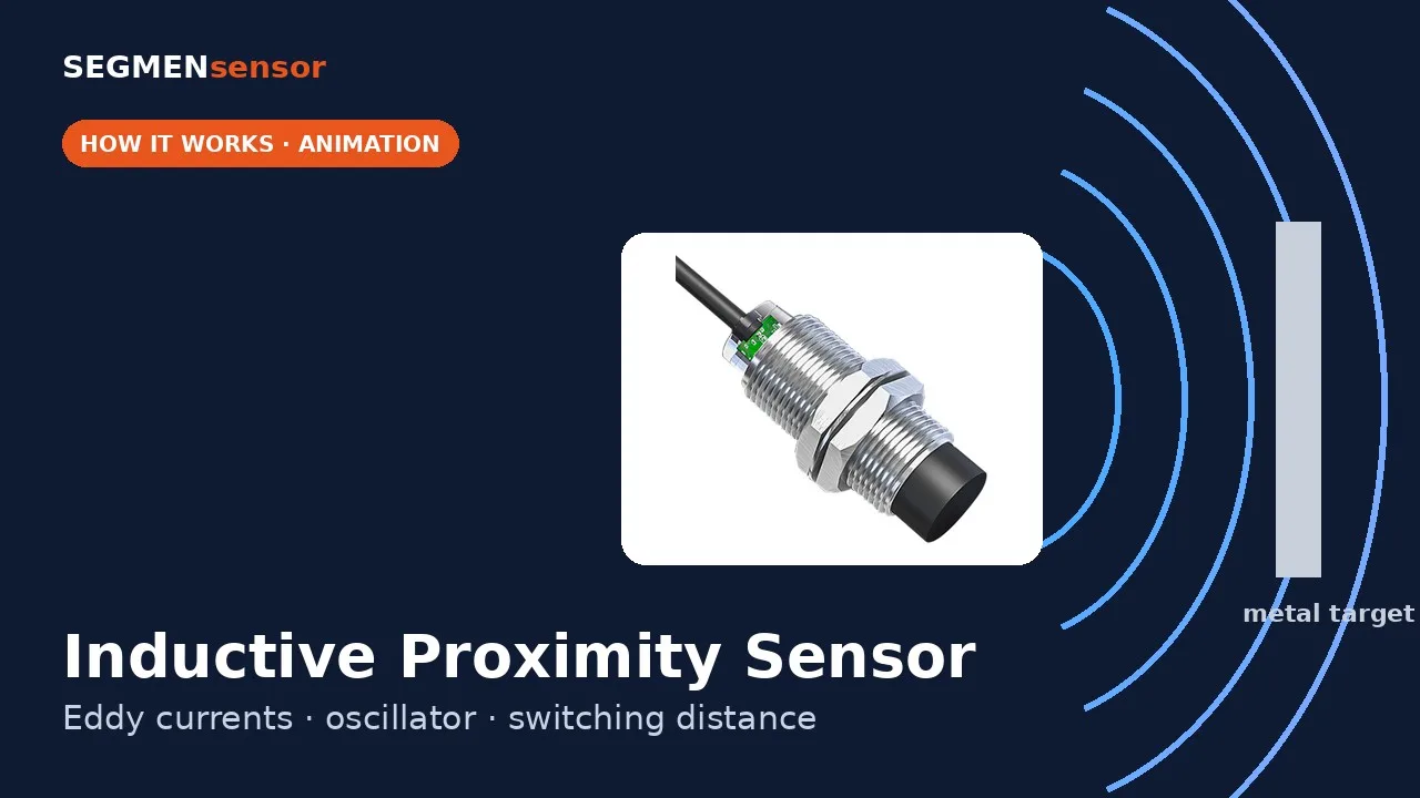
An inductive proximity sensor detects metal without contact in four stages: an LC oscillator drives a coil on a ferrite core to create an alternating magnetic field; a metal target lets eddy currents flow and drain energy from that field; an evaluation circuit sees the oscillation amplitude fall below a threshold; and the output stage (PNP, NPN, 2-wire or AC) switches the load and lights the LED.
What happens inside an inductive proximity sensor, step by step?
Inside the threaded housing there are four functional blocks. The diagram follows the signal from the coil behind the sensing face to the wire that goes to the PLC input.
- Oscillator and coil. A coil wound in a ferrite pot core forms the inductor of an LC oscillator. The open side of the pot core faces the sensing face, so the alternating field bulges out in front of the sensor and is shielded at the sides on flush types.
- Eddy-current damping. When an electrically conductive target enters the field, the changing flux induces circulating eddy currents in its surface. Their resistive loss — the "eddy current loss" defined in IEC 60050 IEV 221-03-23 ↗ — is energy taken from the oscillator, so the amplitude falls as the target comes closer.
- Evaluation. A demodulator turns the high-frequency signal into a DC level proportional to amplitude. A Schmitt trigger switches when that level crosses the switch-on threshold and only switches back at a second, higher threshold.
- Output stage. The trigger drives a transistor: a PNP output sources +V to the load, an NPN output sinks it to 0 V, a DC 2-wire stage switches in series with the load. Most sensors also light a status LED and include short-circuit and reverse-polarity protection.
What sets the oscillator frequency and how deep does the field go?
The oscillator runs at the resonant frequency of its coil and capacitor, and that frequency sets how far the eddy currents reach into the target. Two textbook formulas explain most of the behaviour you see on a machine.
| Quantity | Formula | Worked example (calculated) |
|---|---|---|
| Resonant frequency | f = 1 ÷ (2π √(L·C)) | L = 1 mH, C = 2.2 nF → f ≈ 107 kHz (illustrative values, not a SEGMENsensor design figure) |
| Skin depth | δ = √(ρ ÷ (π · f · μ₀ · μr)) | At 100 kHz: copper ≈ 0.21 mm, aluminium ≈ 0.26 mm, stainless steel 304 ≈ 1.35 mm; mild steel below 0.1 mm (μr ≥ 100 assumed) |
Resistivities used: copper 1.68 × 10⁻⁸ Ω·m, aluminium 2.65 × 10⁻⁸ Ω·m, stainless steel 304 7.2 × 10⁻⁷ Ω·m. Because the eddy currents flow in a surface layer well under 1.5 mm, the 1 mm thick standard target of IEC 60947-5-2 ↗ behaves like a solid block for most metals, while very thin foils can behave differently and should be tested.
Why does an inductive sensor detect steel further than aluminium or copper?
Because mild steel is both ferromagnetic and relatively resistive, it absorbs the most energy from the field, so the oscillator is damped at the longest distance. Copper and aluminium conduct so well that their eddy currents lose little energy and mostly push the field back, so the target must come closer before the amplitude drops enough. Stainless steel 304 is non-magnetic but resistive and sits in between.
| Target metal | Typical reduction factor | M18 flush, Sn = 8 mm: assured distance 0.81 × Sn × factor (calculated) |
|---|---|---|
| Mild steel Fe 360 | 1.00 | ≤ 6.5 mm |
| Stainless steel 304 | 0.65 | ≤ 4.2 mm |
| Aluminium | 0.45 | ≤ 2.9 mm |
| Copper | 0.30 | ≤ 1.9 mm |
Reduction factors are typical values; check the datasheet of the part number. For aluminium, brass or copper targets an all-metal sensor such as the SGI-FM series, made for non-ferrous targets, avoids most of the derating. Sn, Sr, Su and Sa and mounting effects are covered in proximity sensor sensing distance.
Why does the sensor switch off at a longer distance than it switches on?
The two thresholds of the Schmitt trigger create a hysteresis band, so a target vibrating at the switching point does not make the output chatter. IEC 60947-5-2 allows a differential of up to 20% of the real switching distance Sr.
Worked example (calculated): an M18 flush sensor with Sn = 8 mm has a real switching distance Sr between 0.9 × 8 = 7.2 mm and 1.1 × 8 = 8.8 mm. If the sample switches on at Sr = 8.0 mm, a 20% maximum hysteresis means it must switch off again by 8.0 × 1.2 = 9.6 mm. SEGMENsensor high-pressure inductive sensors specify hysteresis below 15% Sr and repeatability below 1.0% Sr.
What can stop an inductive proximity sensor from working?
| Stage affected | Symptom | Typical cause and fix |
|---|---|---|
| Oscillator field | Switches without a target | Non-flush sensor too close to surrounding metal or another sensor; keep the metal-free zone or use a flush type (flush vs non-flush) |
| Target damping | Never switches on aluminium or brass | Reduction factor not allowed for; move closer, use a larger housing or an all-metal sensor |
| Evaluation | Output flickers at end of stroke | Target stops inside the hysteresis band; set the gap to about 0.8 × Sn or less |
| Evaluation | False switching near welding | Strong magnetic fields saturate the ferrite core; use a weld-field immune type (SGI-WR, up to 150 mT) |
| Output stage | LED on, PLC input stays off | PNP/NPN does not match the input type, or DC 2-wire leakage current — see NPN vs PNP wiring |
SEGMENsensor inductive proximity sensors: key data
| Series | Key data (from product pages) |
|---|---|
| SGI-GP general purpose | 6.5 mm to M30, flush or non-flush; Sn 1–50 mm; NPN/PNP 3-wire, DC 2-wire, AC 2-wire, AC/DC; supply 10–30 V DC with ≤ 2.5 V voltage drop (other ranges by output) |
| SGI-HP high pressure | 500 bar (M8/M12), M18 hydraulic-cylinder type 250–1000 bar; hysteresis < 15% Sr |
| SGI-HT high temperature | +120 °C or +150 °C; sensing 1–25 mm |
| SGI-WR weld-field immune | Constant and alternating fields up to 150 mT; M8 to M30 |
| SGI-AO analog | 4–20 mA / 0–10 V output proportional to distance; range up to 10 mm (M12) |
| Samples | Qualification samples 1–5 pcs in 5–7 working days; production lead time and quantities confirmed with the quotation |
Switching frequency, protection class and operating temperature depend on the part number. Decode or build a code with the proximity sensor part number lookup, or download the inductive proximity sensor datasheet (PDF). How the inductive principle compares with other sensing methods is explained in types of proximity sensors and inductive vs capacitive proximity sensors.
Need an inductive sensor for a specific target or mounting point?
Send the target material, the gap, the housing size, the controller input and the conditions at the sensor (pressure, temperature, welding). Our engineers will propose a part number. Qualification samples 1–5 pcs in 5–7 working days · FOB China · reply within 24 hours.
Frequently Asked Questions
No. Only electrically conductive material carries eddy currents, so plastic, wood, glass and liquids do not damp the oscillator. Use a capacitive, photoelectric or ultrasonic sensor for non-metal targets.
No. The sensor makes its own alternating magnetic field, and any metal target damps it. Sensors that need a magnet on the target are magnetic (reed or Hall) sensors, a different type.
IEC 60947-5-2 uses a square plate of mild steel Fe 360, 1 mm thick, whose side equals the diameter of the sensing face or three times Sn, whichever is larger. The rated distance Sn is defined with this target.
Aluminium conducts so well that its eddy currents lose little energy, so the oscillator is damped less at a given gap. A typical reduction factor is 0.45, so an M18 flush sensor with Sn = 8 mm assures about 2.9 mm on aluminium (calculated).
Yes. An analog inductive sensor outputs the oscillator damping as a signal instead of switching at one threshold. SEGMENsensor SGI-AO models give 4–20 mA or 0–10 V over a range of up to 10 mm (M12).