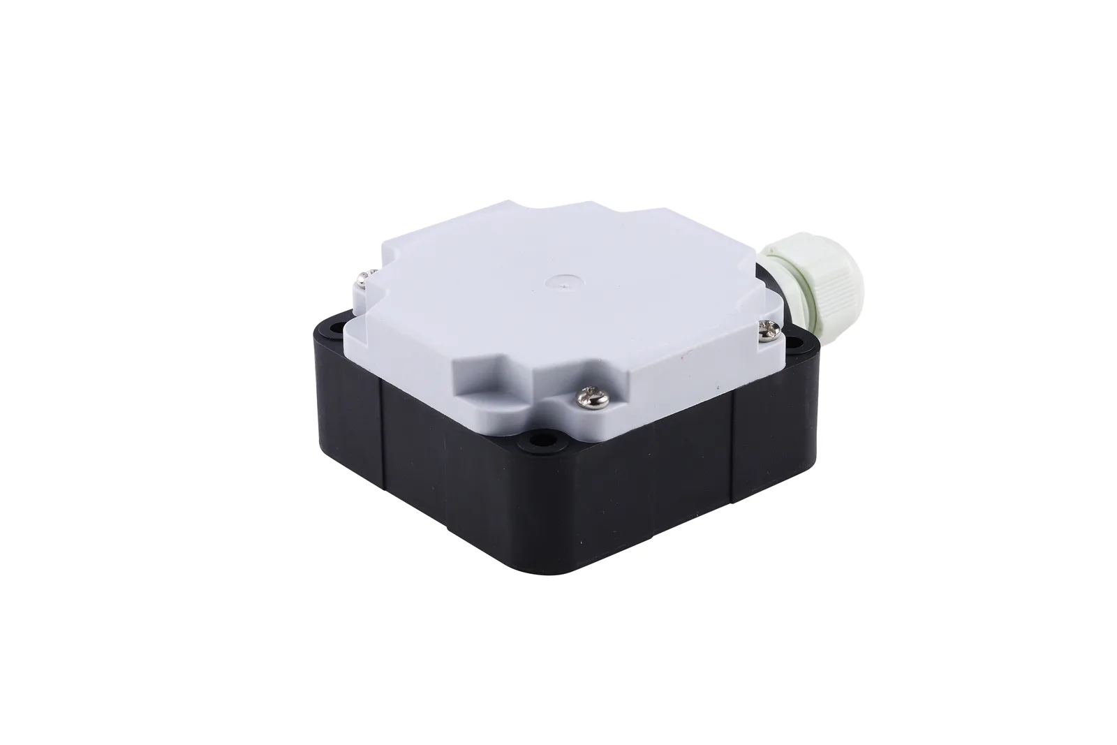
NPN (sinking): Brown → +24 V, Blue → 0 V, Black (output) → PLC input. PLC input common → +24 V. Output pulls to 0 V when active.
PNP (sourcing): Brown → +24 V, Blue → 0 V, Black (output) → PLC input. PLC input common → 0 V. Output drives to +24 V when active.
Match the sensor output type to the PLC input type: NPN sensor → sinking (NPN) PLC input; PNP sensor → sourcing (PNP) PLC input.
NPN vs PNP: The Core Difference
The terms NPN and PNP describe the transistor type used in the proximity sensor's output stage, which determines how the output switches relative to the power supply:
| Property | NPN (Sinking) | PNP (Sourcing) |
|---|---|---|
| Output when active | Pulls output to 0 V (GND) | Drives output to +Vcc (+24 V) |
| Current flow | Current sinks INTO the sensor | Current sources OUT from the sensor |
| PLC input type | NPN / Sinking input (common = +24 V) | PNP / Sourcing input (common = 0 V) |
| Geographic standard | Japan, Asia, some NA | Europe, North America |
| Wire colours (IEC 60947-5-2) | BN=+Vcc, BU=0V, BK=output | BN=+Vcc, BU=0V, BK=output |
The wire colours are identical — the difference is only in how the output transistor switches, and therefore how the PLC input common must be connected.
Wiring an NPN 3-Wire Proximity Sensor
An NPN (sinking) proximity sensor has an open-collector NPN transistor output. When the sensor detects an object, the transistor turns ON and the Black output wire is pulled DOWN to 0 V. The load (PLC input, relay coil, or indicator lamp) connects between the Black wire and +24 V.
- For NPN sensors, the PLC input COMMON must be wired to +24 V (not to 0 V).
- This is the single most common wiring mistake — connecting PLC common to 0 V with an NPN sensor results in no signal or inverted logic.
- Check your PLC manual: NPN inputs are also labelled "Sink" or "Current Sink" on the terminal block.
Wiring a PNP 3-Wire Proximity Sensor
A PNP (sourcing) proximity sensor has an open-collector PNP transistor output. When the sensor detects an object, the transistor turns ON and the Black output wire is driven UP to +24 V. The load connects between the Black wire and 0 V.
NO vs NC Output: Normally Open and Normally Closed
Both NPN and PNP sensors can have Normally Open (NO) or Normally Closed (NC) output logic. This is independent of the NPN/PNP transistor type:
| Output Type | No Object in Range | Object Detected | Typical Use |
|---|---|---|---|
| NO (Normally Open) | Output OFF | Output ON | Object detection, counting, position sensing |
| NC (Normally Closed) | Output ON | Output OFF | Safety circuits, wire-break detection (fail-safe) |
A 4-wire sensor provides both NO and NC outputs simultaneously on separate wires (Brown, Blue, Black, White), allowing both logic functions from one sensor without wiring two sensors.
Standard Wire Colour Code (IEC 60947-5-2)
| Wire | Colour | Function |
|---|---|---|
| 3-wire sensors | Brown (BN) | +Vcc (positive supply, typically +24 V DC) |
| Blue (BU) | 0 V (negative supply / ground) | |
| Black (BK) | Output signal (switching output) | |
| 4-wire sensors | Brown (BN) | +Vcc |
| Blue (BU) | 0 V | |
| Black (BK) | Output 1 (NO) | |
| White (WH) | Output 2 (NC) |
Frequently Asked Questions
An NPN sensor pulls the output DOWN to 0 V when active (current sinking). A PNP sensor drives the output UP to +24 V when active (current sourcing). NPN is standard in Japan and Asia; PNP is standard in Europe and North America. Match the sensor output type to the PLC input type: NPN sensor → PLC NPN sinking input; PNP sensor → PLC PNP sourcing input.
Connect Brown to +24 V, Blue to 0 V, Black (output) to the PLC input terminal. Connect the PLC input's common terminal to +24 V (not 0 V — this is the key difference for NPN sinking inputs). When the sensor detects an object, the Black wire pulls to 0 V, which the PLC reads as an active input.
Connect Brown to +24 V, Blue to 0 V, Black (output) to the PLC input terminal. Connect the PLC input's common terminal to 0 V. When the sensor detects an object, the Black wire is driven to +24 V, which the PLC reads as a HIGH active input.
NO (Normally Open) means the output is OFF when no object is detected, and switches ON when an object is in range. NC (Normally Closed) is the opposite: ON with no object, OFF when an object is detected. NO is used for object detection and counting; NC is used for safety circuits where a broken wire should trigger an alarm (fail-safe wiring).
Not directly. Use a PNP-to-NPN converter relay module, replace the sensor with the correct NPN output type, or use a sensor with selectable NPN/PNP output. Always match sensor output type to PLC input type for correct operation.
Per IEC 60947-5-2: Brown (BN) = +Vcc (+24 V), Blue (BU) = 0 V ground, Black (BK) = switching output. For 4-wire sensors: Brown = +Vcc, Blue = 0 V, Black = output 1 (NO), White = output 2 (NC). This colour code is used by SEGMENsensor and most European and Asian manufacturers.
Standard 3-wire DC proximity sensors drive cable runs up to 200–300 metres with shielded cable (0.34 mm² or larger). For longer runs or noisy environments near VFDs, use shielded cable with the shield grounded at one end. Verify that voltage drop on the Brown (+Vcc) wire does not drop below the sensor's minimum supply voltage for runs over 100 m.