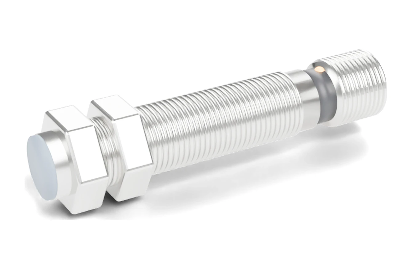
M12 A-coded, 4-pin sensor connector: Pin 1 = brown = +V (L+) · Pin 2 = white = second output / NC / diagnostic · Pin 3 = blue = 0 V (L−) · Pin 4 = black = switching output (NO).
A 3-wire NPN or PNP sensor uses pins 1, 3 and 4 only. Always confirm against the pin drawing on the sensor label or datasheet, because 2-wire, analog and special-function sensors can differ.
What is the M12 A-coded pinout for a 3-wire or 4-wire sensor?
For DC proximity sensors, photoelectric sensors and other switching sensors, pins 1, 3 and 4 always carry supply and the main output. The wire colours on a moulded M12 cordset match the colours of a cable-version sensor, so a brown-blue-black wiring diagram reads the same whether the sensor has a fixed cable or a connector.
| Pin | Cordset wire colour | 3-wire DC (NPN / PNP) | 4-wire DC (NO + NC) | IO-Link device (port class A) |
|---|---|---|---|---|
| 1 | Brown (BN) | +V supply (L+) | +V supply (L+) | L+ (24 V) |
| 2 | White (WH) | Not connected | Output 2, NC | DI / DO (extra switching channel) |
| 3 | Blue (BU) | 0 V (L−) | 0 V (L−) | L− (0 V) |
| 4 | Black (BK) | Switching output (NO or NC) | Output 1, NO | C/Q (IO-Link communication or switching output) |
| 5 (5-pin only) | Grey (GY) | Not used / functional earth | Not used / functional earth | Not used in port class A |
The NPN or PNP type does not change the pin numbers. An NPN output on pin 4 switches to 0 V when the target is present; a PNP output on pin 4 switches to +V. How each one connects to a sinking or sourcing PLC input is shown in NPN vs PNP proximity sensor wiring.
What do A, B, D and X coding mean on an M12 connector?
Coding is a mechanical key and keyway that stops a connector being plugged into the wrong kind of circuit. Sensors and actuators use A coding; the others are for networks or power.
| M12 coding | Typical use | Common pin counts | Standard |
|---|---|---|---|
| A | Sensors, actuators, DC power, IO-Link | 3, 4, 5, 8, 12 | IEC 61076-2-101 |
| B | Fieldbus (e.g. PROFIBUS DP) | 5 | IEC 61076-2-101 |
| D | Industrial Ethernet, 100 Mbit/s | 4 | IEC 61076-2-101 |
| X | Industrial Ethernet, up to 10 Gbit/s | 8 | IEC 61076-2-109 |
| K, L, S, T | AC / DC power distribution | 4–5 | IEC 61076-2-111 |
A 4-pin A-coded cordset fits a 3-pin A-coded sensor plug, because the 3-pin version simply omits pin 2. A B-, D- or X-coded cable will not mate with an A-coded sensor.
How do you check an M12 pinout before wiring a sensor?
- Read the label or datasheet. Every SEGMENsensor part number has its M12 pin assignment on the label and in the M12 flush inductive proximity sensor datasheet (PDF).
- Identify the output code. In SEGMENsensor part numbers, NA / NB = NPN NO / NC, PA / PB = PNP NO / NC, NC / PC = NO + NC (4-wire), DA / DB = DC 2-wire NO / NC.
- Measure the supply. With the cordset plugged in, check brown (pin 1) to blue (pin 3) is within the supply range, 10–30 V DC for standard SGI-GP 3-wire models.
- Test the output. Bring a steel target inside the rated sensing distance and check that pin 4 (black) switches and the LED changes state.
| Symptom | Likely cause | What to do |
|---|---|---|
| LED off, no output | Supply on wrong pins, or cordset not fully screwed in | Check +V on pin 1 (brown) and 0 V on pin 3 (blue); tighten the coupling nut |
| LED switches, PLC sees nothing | NPN sensor on a sourcing input or PNP on a sinking input | Match output type to PLC input common (see wiring guide) |
| Signal only on white wire | NC or second output used instead of pin 4 | Move the PLC input to the black wire (pin 4), or order the NO version |
| Cordset will not plug in | Different coding (B, D or X) or M8 vs M12 thread | Use an A-coded M12×1 cordset |
Which SEGMENsensor sensors come with an M12 connector?
The Q4 suffix in a SEGMENsensor part number means an M12 connector; C2 means a 2 m fixed cable. The pin assignment above applies to the 3-wire and 4-wire examples below. DC 2-wire and analog-output models use their own assignment, shown on their datasheets.
| Part number | Housing / mounting | Sensing range | Output | Pins used | Series page |
|---|---|---|---|---|---|
| SGI-GP12S-040PA-Q4 | M12, flush | 4 mm | PNP NO, 10–30 V DC | 1, 3, 4 | M12 flush |
| SGI-GP12S-040NA-Q4 | M12, flush | 4 mm | NPN NO, 10–30 V DC | 1, 3, 4 | M12 flush |
| SGI-GP12S-040PC-Q4 | M12, flush | 4 mm | PNP NO + NC, 10–30 V DC | 1, 2, 3, 4 | M12 flush |
| SGI-GP18S-050PA-Q4 | M18, flush | 5 mm | PNP NO, 10–30 V DC | 1, 3, 4 | M18 flush |
| SGI-GP30S-100PA-Q4 | M30, flush | 10 mm | PNP NO, 10–30 V DC | 1, 3, 4 | M30 flush |
| SGI-HP12S-015PA-Q4-L69 | M12, flush, high pressure | 1.5 mm | PNP NO, 10–30 V DC | 1, 3, 4 | High-pressure series |
| SGI-AO12S-040I-Q4 | M12, flush, analog | 0.5–4.0 mm | 4–20 mA, 18–30 V DC | See datasheet | Analog output |
For a 4–20 mA loop, the 4–20 mA loop resistance calculator checks whether the supply can drive the cable and PLC input. Mounting choice is covered in flush vs non-flush proximity sensors, and the full range is on the inductive proximity sensor page.
To get a quotation, send the housing size, flush or non-flush mounting, sensing distance, output code, M12 connector or cable, supply voltage and estimated annual volume. Qualification samples of 1–5 pcs ship in 5–7 working days; production lead time and MOQ are confirmed with the quotation. Trade terms are FOB China with 100% T/T in advance, and we reply within 24 hours.
Frequently Asked Questions
Pin 1 is the positive supply (+V, L+). On a standard M12 cordset it is the brown wire. For standard SEGMENsensor SGI-GP 3-wire sensors the supply is 10–30 V DC.
Pin 4, the black wire, carries the switching output on 3-wire NPN and PNP sensors. Pin 1 (brown) is +V, pin 3 (blue) is 0 V, and pin 2 is not connected.
Pin 2 carries a second signal: the NC output on a 4-wire NO + NC sensor, a diagnostic or alarm output on some sensors, or the extra DI / DO channel on IO-Link devices. On a plain 3-wire sensor it is not connected.
A coding is used for sensors, actuators, DC power and IO-Link. D coding is a 4-pin layout for 100 Mbit/s industrial Ethernet. The keyways are different, so the two cannot be plugged together.
Yes, if both are A-coded. Pins 1 to 4 line up, and the grey pin 5 wire of the cable is left unused. A 4-pin cable on a 5-pin sensor works only if the sensor does not need pin 5.
Choose a part number ending in Q4, which means M12 connector. For example, SGI-GP12S-040PA-Q4 is an M12 flush, 4 mm, PNP NO sensor. Qualification samples of 1–5 pcs ship in 5–7 working days; production lead time and MOQ are confirmed with the quotation.