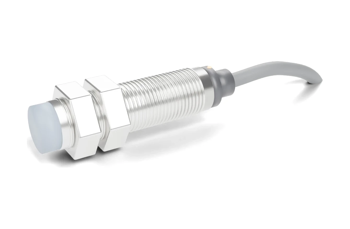
Choose a flush sensor when the head must sit inside a steel bracket, end cap or machine frame, or when sensors are mounted close together. Choose a non-flush sensor when you need more distance between the face and the target and you can leave the head protruding with clear space around it. Same housing size, same output — only the mounting and the sensing distance change.
Every cylindrical inductive proximity sensor is built in one of two ways: with a metal shield around the coil (flush) or without it (non-flush). The choice decides how far the sensor reaches, how it must be mounted and how close two sensors may sit. This page explains the difference, shows the sensing distances of the SEGMENsensor SGI-GP inductive proximity sensor series side by side, and works through a selection example. The figures come from the SEGMENsensor part-number table (4,060 checked SGI-GP part numbers).
What Is the Difference Between a Flush and a Non-Flush Proximity Sensor?
A flush sensor's field is confined to the front by a shield, so surrounding metal does not disturb it; a non-flush sensor's field also spreads sideways, so it reaches farther but reacts to metal beside the head. IEC 60947-5-2 — Proximity switches ↗ uses the terms embeddable and non-embeddable for the two types and defines the free zone that must stay clear of metal.
| Item | Flush | Non-flush |
|---|---|---|
| Other names | Shielded, embeddable | Unshielded, non-embeddable |
| Construction | Metal band around the coil; face level with the housing thread | No side shield; coil cap protrudes beyond the thread |
| Field shape | Focused forward | Wider, also to the sides |
| Rated sensing distance (SGI-GP) | 1–25 mm (M8 to M30) | 2–50 mm (M8 to M30) |
| Mounting in metal | Face may sit level with the bracket | Face must protrude; metal-free zone around the head |
| Side-by-side spacing | Closer spacing possible | Wider spacing needed |
| Exposure of the head | Protected by the bracket | Exposed to chips and knocks |
| SGI-GP part-number code | S (e.g. SGI-GP12S-040PA-Q4) | U (e.g. SGI-GP18U family) |
Why Does a Non-Flush Sensor Sense Farther?
Because nothing around the coil absorbs or bends its field. In an inductive sensor an oscillator drives a coil on a ferrite core; a metal target entering the field takes energy through eddy currents and the output switches (background on eddy currents in conductive materials: NIST/NBS Special Publication 589, Eddy current nondestructive testing ↗). The shield of a flush sensor keeps the field off the bracket, but it also makes the usable field smaller. Remove the shield and the same coil projects its field farther forward and to the sides.
How Much Farther? SGI-GP Sensing Distances by Housing Size
Across the SGI-GP series the non-flush rated distance is 1.5 to 2.0 times the flush distance of the same housing (calculated from the values below; mild steel target, as defined for the rated distance Sn).
| Housing | Flush Sn | Non-flush Sn | Longest non-flush ÷ longest flush (calculated) | Part numbers (flush / non-flush) |
|---|---|---|---|---|
| 6.5 mm | 1 / 2 / 3 / 4 mm | 2 / 4 / 6 / 8 mm | 2.0 | 609 / 569 |
| M8 | 1 / 2 / 3 / 4 mm | 2 / 4 / 6 / 8 mm | 2.0 | 549 / 579 |
| M12 | 2 / 4 / 6 / 8 mm | 4 / 8 / 10 / 12 mm | 1.5 | 329 / 327 |
| M18 | 5 / 8 / 12 / 15 mm | 8 / 16 / 20 / 23 mm | 1.5 | 303 / 302 |
| M30 | 10 / 16 / 22 / 25 mm | 15 / 25 / 40 / 50 mm | 2.0 | 246 / 247 |
Family pages with filters and datasheets: M8 flush · M12 flush · M18 flush · M18 non-flush · M30 flush. A few M12 short-housing part numbers are listed as semi-flush; their mounting is shown on the dimension drawing. To decode any part number, use the proximity sensor part number lookup.
Worked Example: Flush or Non-Flush for a 10 mm Gap?
IEC 60947-5-2 defines the assured operating distance Sa as 0 to 81 % of the rated distance Sn, so design the target to pass within Sa = 0.81 × Sn.
Task: detect a mild steel bracket passing 10 mm in front of an M18 sensor.
- M18 flush, Sn = 12 mm: Sa = 0.81 × 12 = 9.7 mm (calculated). Less than 10 mm — not reliable.
- M18 flush, Sn = 15 mm: Sa = 0.81 × 15 = 12.2 mm (calculated). Works, with 2.2 mm margin, and the head can sit level in the bracket.
- M18 non-flush, Sn = 16 mm: Sa = 0.81 × 16 = 13.0 mm (calculated). Works with 3.0 mm margin, but the head must protrude with metal-free space around it.
If the target is aluminium, stainless steel or copper, apply the material reduction factor first: see the reduction-factor example in types of proximity sensors and the Sn, Sr, Su and Sa definitions in proximity sensor sensing distance.
Which One Should You Choose?
Start from the mounting, then check the distance. If the head has to sit inside metal, the answer is flush, and the gap must be designed around the flush Sa.
| Situation | Choose | Why |
|---|---|---|
| Sensor screwed into a steel plate, end cap or frame | Flush | Surrounding metal would damp a non-flush field |
| Hydraulic cylinder end position | Flush, pressure-rated | The head sits in the steel end cap; all SGI-HP high-pressure sensors are flush |
| Several sensors close together | Flush | Narrower field, less interaction between neighbours |
| Target passes beyond the flush Sa | Non-flush | 1.5–2 × the distance in the same housing |
| Head exposed to chips or knocks | Flush | The bracket protects the face |
| Conveyor, pallet or can detection with room around the head | Non-flush | Longer distance tolerates position variation |
How Do You Mount Each Type?
Mount a flush sensor with its face level with the bracket; mount a non-flush sensor so the face protrudes beyond the bracket. In both cases keep the zone in front of the face clear of metal other than the target, and take the minimum clearances and side-by-side spacing from the part number's dimension drawing.
| Symptom | Likely cause | Fix |
|---|---|---|
| Output stays on, or range is much shorter than rated | Non-flush sensor buried in metal | Let the head protrude as drawn, or change to a flush model |
| Output flickers when two sensors are close | Fields of neighbouring sensors interact | Increase spacing to the drawing value or use flush models |
| Target is never detected | Flush sensor with gap beyond 0.81 × Sn | Move the target closer or choose a longer Sn / non-flush model |
After mounting, power the sensor and move the target into position: the LED must switch on at the working gap and reset when the target moves away. For NPN or PNP wiring, see NPN vs PNP proximity sensor wiring.
- Housings: 6.5 mm, M8, M12, M18, M30; flush or non-flush.
- Rated sensing distance: 1 mm (6.5 mm and M8 flush) to 50 mm (M30 non-flush).
- Outputs: NPN or PNP 3-wire, DC 2-wire, AC 2-wire (M18, M30), AC/DC (M12, M18, M30); NO, NC or NO + NC.
- Supply: 10–30 V DC, 5–36 V DC, 10–55 V DC, 10–60 V DC; 20–250 V AC or AC/DC on AC models.
- Connection: 2 m cable, M8 or M12 connector, or pigtail (by size).
- Housing: nickel-plated brass; stainless steel or PBT on some sizes.
Download the inductive proximity sensor datasheet (PDF)
Sensing distances, outputs, supply voltages, dimensions, wiring and ordering codes for flush and non-flush models. No registration required.
Not sure which mounting fits your bracket?
Send the housing size, the gap to the target, the target material, the bracket drawing and your annual volume. Our engineers will propose flush or non-flush part numbers. Qualification samples 1–5 pcs in 5–7 working days · production lead time and MOQ confirmed with the quotation · reply within 24 hours.
Factory-Direct Proximity Sensor Supply for OEMs
SEGMEN (Shenzhen) Industrial Development Co., Ltd. has manufactured sensors in Shenzhen since 2019. Every SGI-GP configuration, flush or non-flush, is a fixed part number, so the mounting type is printed on the label, the datasheet and your purchase order. Inductive proximity sensors are CE and RoHS compliant. Quotations are FOB China with 100% T/T in advance, and every RFQ is answered within 24 hours. Standards background: IEC 60947-5-2 is also published in North America as CSA C22.2 No. 60947-5-2 (Standards Council of Canada) ↗.
Frequently Asked Questions
Yes. Flush, shielded and embeddable describe the same construction: a metal band around the coil lets the face sit level with surrounding metal. Non-flush, unshielded and non-embeddable describe the type without that band.
No. The surrounding metal damps its field, so the output may stay on or the range becomes much shorter than rated. Let the head protrude as shown on the dimension drawing, or use a flush model.
In SEGMENsensor SGI-GP data, 1.5 to 2 times the flush distance of the same housing: for example M18 is rated up to 15 mm flush and up to 23 mm non-flush, and M30 up to 25 mm flush and up to 50 mm non-flush.
Look at the letter after the housing size: S means flush and U means non-flush. SGI-GP12S is an M12 flush sensor; SGI-GP18U is an M18 non-flush sensor.
Flush. The sensor head sits in the steel end cap, and it must also be pressure-rated. All SEGMENsensor SGI-HP high-pressure inductive sensors are flush.
Qualification samples of 1–5 pcs ship in 5–7 working days. Production lead time and MOQ are confirmed with the quotation, which is FOB China and answered within 24 hours.
Related reading: Inductive proximity sensors — product page · Proximity sensor sensing distance · Types of proximity sensors · Inductive vs capacitive proximity sensors · Hydraulic cylinder end-position detection
Last updated: 24 October 2026. Specifications reflect the SEGMENsensor SGI-GP part-number table at the time of writing; calculated values are marked as such.