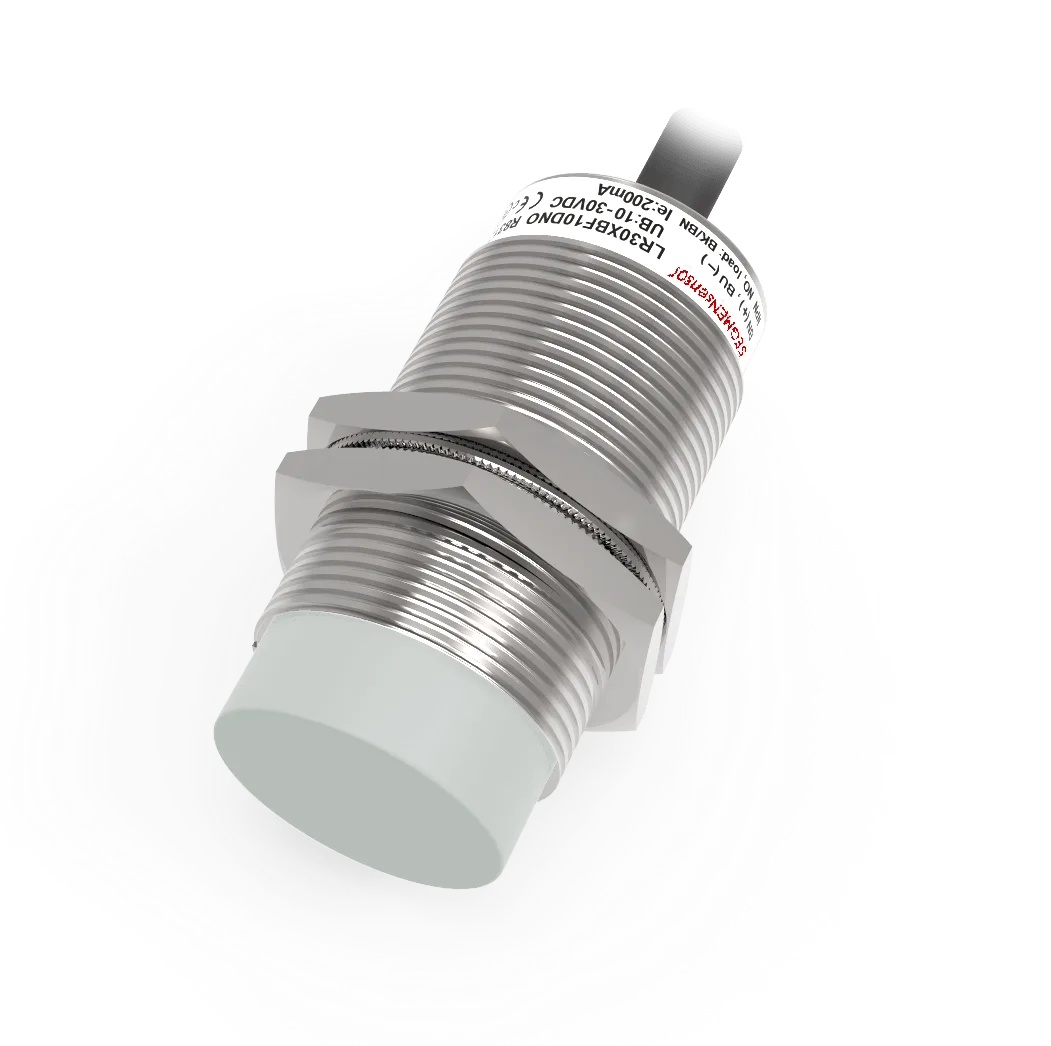
Sn (nominal) is the datasheet value measured in lab conditions. In real applications, design with Sa = 0.72 × Sn — the assured range valid across manufacturing tolerances, temperature (−25°C to +70°C), and voltage variation. Then multiply by the target material's reduction factor: aluminium ≈ 0.45, stainless steel 304 ≈ 0.65, copper ≈ 0.30. A 10 mm Sn sensor reliably detects mild steel at 7.2 mm, aluminium at 3.2 mm.
Sensing Distance Terminology: Sn, Sr, Su, Sa Defined
The IEC 60947-5-2 standard defines four sensing distance parameters for inductive proximity sensors. Understanding the difference prevents the most common commissioning mistake: designing to Sn and finding that the sensor does not reliably detect in the field.
| Symbol | Name | Definition | Typical Value | Use For |
|---|---|---|---|---|
| Sn | Nominal Sensing Distance | Theoretical design value — measured with standard mild steel target, 20°C, nominal voltage, ideal installation | 100% (reference) | Specification comparison only |
| Sr | Real Sensing Distance | Measured switching point in lab — accounts for actual production variance. Must be 90–110% of Sn per IEC 60947-5-2 | 90–110% Sn | Lab verification only |
| Su | Usable Sensing Distance | Operating range accounting for manufacturing tolerances and temperature effects (−25°C to +70°C) | 0–81% Sn | Engineering margin reference |
| Sa | Assured Sensing Distance | Guaranteed reliable working range — valid for all production units across full temperature range and supply voltage variation | 0–72% Sn | Always design to Sa |
Material Reduction Factor: Complete Reference Table
Inductive proximity sensors generate eddy currents in conductive targets. The magnitude of those currents — and therefore the sensor's ability to detect the target — depends on the target material's electrical conductivity and magnetic permeability. Mild steel (Fe 360) is the reference material (factor = 1.00). All other metals produce smaller or larger eddy currents.
This table covers 16 common industrial materials. Values are based on standard M18 sensor tests; actual values may vary ±10% depending on sensor design and target geometry.
| Target Material | Reduction Factor (RF) | Detection vs. Steel | Typical Example | Reliability |
|---|---|---|---|---|
| Mild Steel (Fe 360) | 1.00 | 100% | Structural steel, machine frames | Excellent |
| Cast Iron | 0.90–1.00 | 90–100% | Machine housings, pump bodies | Excellent |
| Chromium Steel (hardened) | 0.85–0.95 | 85–95% | Shafts, bearings, hydraulic rods | Excellent |
| Stainless Steel 430 (ferritic) | 0.75–0.85 | 75–85% | Food equipment, tanks | Good |
| Stainless Steel 316 (austenitic) | 0.60–0.70 | 60–70% | Chemical vessels, marine | Moderate |
| Stainless Steel 304 (austenitic) | 0.60–0.70 | 60–70% | Food processing, HVAC | Moderate |
| Nickel Alloy (Inconel) | 0.55–0.70 | 55–70% | High-temp furnace parts | Moderate |
| Zinc (galvanised) | 0.50–0.60 | 50–60% | Sheet metal, automotive body | Moderate |
| Aluminium (general) | 0.40–0.50 | 40–50% | Extrusions, machined parts, fixtures | Reduced |
| Aluminium Alloy (high Si) | 0.35–0.45 | 35–45% | Die-cast housings, engine blocks | Reduced |
| Titanium | 0.45–0.55 | 45–55% | Aerospace, medical implants | Reduced |
| Brass | 0.30–0.40 | 30–40% | Fittings, valves, connectors | Low |
| Copper (pure) | 0.25–0.35 | 25–35% | Busbars, wire, heat exchangers | Low |
| Bronze | 0.30–0.40 | 30–40% | Bearings, marine fittings | Low |
| Lead | 0.20–0.30 | 20–30% | Radiation shielding, batteries | Very low |
| Non-metallic (plastic, wood) | 0 | 0% | Any non-conductive material | Not detectable |
- For aluminium: choose a sensor with Sn at least 2× the required detection distance to maintain Sa margin after the 0.45 reduction factor.
- For copper or brass: choose Sn at least 3× the required distance — or use a sensor with an "all-metal" factor-1 design (available in SEGMENsensor M18/M30 range).
- Always test with the actual production target, as surface condition (oxide layer, plating, surface roughness) affects eddy current generation and can shift RF by ±10%.
Flush vs Non-Flush Mounting: How Installation Affects Sensing Range
The installation type — flush or non-flush — is the second biggest factor affecting real-world sensing distance, after target material.
Flush (Shielded) Sensors
- Metal shield around the coil focuses field forward
- Can be installed level with surrounding metal surface
- Typically 15–25% shorter Sn than non-flush equivalent size
- No lateral metal-free zone required
- Better immunity to nearby metal objects
- Use when mounting in metal brackets, fixtures, or tooling
- Standard for most machine tool and automation applications
Non-Flush (Unshielded) Sensors
- No side shielding — field extends laterally
- Longer Sn (typically 1.5–2× flush equivalent)
- Requires metal-free zone ≥ 3× sensor diameter on all sides
- Between two sensors: ≥ 3× diameter axis-to-axis spacing
- Risk of false triggering from nearby metal structures
- Use when maximum sensing range is needed and mounting space allows
- Common for long-range position detection on conveyors
| Sensor Size | Flush Sn (typical) | Non-Flush Sn (typical) | Min. Metal-Free Zone (non-flush) |
|---|---|---|---|
| M8 | 1.5–2 mm | 3–4 mm | 24 mm |
| M12 | 2–4 mm | 4–8 mm | 36 mm |
| M18 | 5–8 mm | 10–16 mm | 54 mm |
| M30 | 10–15 mm | 20–30 mm | 90 mm |
Temperature Effects on Sensing Distance
Temperature changes the electrical resistance of the sensor coil and the magnetic permeability of the ferrite core, both of which shift the oscillation frequency and therefore the switching point. Most sensors lose sensing distance as temperature rises above 20°C.
| Temperature | Typical Sensing Distance Change | IEC 60947-5-2 Compliance | Recommendation |
|---|---|---|---|
| −25°C | Slight increase (+2–5%) | Within Su | No action needed |
| 20°C (standard) | Reference (100%) | Sn reference point | Datasheet value applies |
| 40°C | −3 to −5% | Within Sa | No action needed |
| 60°C | −7 to −12% | Approaching Su limit | Verify Sa margin is maintained |
| 70°C | −10 to −15% | At Su/Sa boundary | Choose next size larger Sn |
| 85°C (extended range) | −15 to −25% | Outside standard Su | Use high-temp rated sensor |
- Standard proximity sensors are rated to 70°C ambient. At 85°C, sensing distance may drop 20–25%, causing intermittent detection failures.
- SEGMENsensor offers high-temperature M18/M30 sensors rated to 120°C with reinforced cable insulation for oven, furnace, and engine bay applications.
- In high-vibration + high-temperature environments, do not rely on a single sensor positioned at exactly the Sa limit — add 30–50% additional margin.
7-Step Sensing Distance Selection Guide
- 1Identify the target material. Look up the reduction factor (RF) in the table above. If the material is not listed, test with a sample — start with RF = 0.35 as a conservative estimate for unknown non-ferrous metals.
- 2Measure the maximum physical gap between the sensor face and the target in your installation. This is your required reliable detection distance (D_required).
- 3Add a safety margin of 20%. D_design = D_required × 1.2. This accounts for target position variation, mounting tolerances, and connector wear over time.
- 4Calculate minimum required Sn. Sn_min = D_design / (0.72 × RF). Example: D_required = 3 mm, aluminium (RF = 0.45): Sn_min = 3.6 / (0.72 × 0.45) = 3.6 / 0.324 = 11.1 mm → choose M18 with Sn = 12 mm.
- 5Select the sensor size (M8/M12/M18/M30) based on Sn_min and the physical space available for mounting. Flush sensors require less lateral clearance but have shorter Sn.
- 6Verify temperature margin. If ambient exceeds 60°C, recalculate with a 15% derating on the sensing distance or select the next larger size. Check the sensor's maximum temperature rating.
- 7Test with the actual target before production. Sensor face debris, surface oxide, and target surface finish can shift sensing distance ±15%. Confirm reliable switching at D_required with the actual target in the actual mounting position.
Common Sensing Distance Problems & Solutions
| Problem | Root Cause | How to Confirm | Solution |
|---|---|---|---|
| Sensor won't detect at specified distance | Wrong material RF, non-flush mounting, exceeding temperature limit, or designing to Sn instead of Sa | Test with mild steel target at room temperature — if it detects at Sn, the issue is material or environment | Apply RF correction; design to Sa × RF; choose larger Sn sensor |
| Intermittent detection (works sometimes) | Target position variation brings it in/out of Sa boundary; vibration; temperature cycling | Check gap variation during machine cycle with a dial gauge or laser; monitor ambient temperature | Reduce gap variation; add 30–50% margin above Sa × RF; use vibration-dampening mount |
| False triggering (activates with no target) | Nearby metal in non-flush sensor's lateral field; mutual interference between adjacent sensors; electrical noise | Remove nearby metal objects one by one; check if two sensors are within 3× diameter of each other | Increase metal-free zone; switch to flush sensor; increase sensor-to-sensor spacing |
| Works in lab, fails on machine | Machine frame acts as metal background reducing effective sensing range; temperature higher than expected; oil/coolant on sensor face | Test sensor in-situ with machine frame present; measure temperature at sensor location during operation | Account for background metal in Sn selection (use 50% of lab range); clean sensor face; use flush type |
| Sensing distance decreases over time | Oil, coolant, or metallic swarf on sensor face reducing field penetration; cable damage; connector corrosion | Clean the sensing face and re-test. Check cable continuity and connector contacts. | Clean sensing face with dry cloth; seal cable entry points; use IP68 sensors in washdown environments |
Frequently Asked Questions
Sn (Nominal) is the datasheet design value measured in ideal lab conditions. Sr (Real) is the actual measured switching point — must be 90–110% of Sn. Su (Usable) is the operating range including manufacturing tolerances and temperature effects, expressed as 0–81% of Sn. Sa (Assured) is the guaranteed range for all production units across the full temperature range: 0–72% of Sn. Always design to Sa — never to Sn — to ensure reliable detection in all real-world conditions.
Sn is measured with mild steel at 20°C in ideal conditions. In practice: non-mild-steel targets reduce range (aluminium = 45%, copper = 30%); installation without proper metal-free zones affects non-flush sensors; temperature above 20°C reduces distance 5–15%; designing to Sn instead of Sa leaves no margin. Design with Sa (72% of Sn) multiplied by the target's reduction factor as your maximum reliable working distance.
Aluminium has a reduction factor of 0.40–0.50 (40–50% of the mild steel sensing distance). A sensor with 10 mm Sn on mild steel detects aluminium at approximately 4–5 mm (before Sa correction). After applying Sa: 10 × 0.72 × 0.45 = 3.2 mm reliable working distance. High-silicon aluminium alloys (die-cast) are at the lower end of this range. Always verify with the actual target alloy.
A flush (shielded) sensor has a metal ring around the coil that focuses the magnetic field forward, allowing installation level with surrounding metal without false triggering from the mounting structure. Sensing distance is 15–25% shorter than a non-flush sensor of the same size. A non-flush (unshielded) sensor has no side shielding, giving longer range but requiring a metal-free zone of at least 3× the sensor diameter around the sensing face to prevent false triggering from mounting hardware.
Sensing distance decreases as temperature rises, typically −0.1% to −0.3% per °C above 20°C. At 70°C (the standard upper limit of Su), distance may be 10–15% less than at 20°C. The IEC 60947-5-2 Su specification (0–81% of Sn) is valid for −25°C to +70°C. Above 70°C, use high-temperature rated sensors. For applications with wide temperature swings, always design to Sa and add further margin if ambient exceeds 60°C.
For non-flush sensors: maintain a metal-free zone of at least 3× the sensor diameter on all sides of the sensing face. M18 non-flush → 54 mm metal-free zone. Between two adjacent non-flush sensors: minimum 3× sensor diameter axis-to-axis spacing to prevent mutual interference. Flush sensors are more forgiving — they can be installed in metal to within 1× their diameter on the sides, with no axis-to-axis restriction when mounted in ferrite-shielded locations.
No — inductive proximity sensors require electrically conductive (metal) targets to generate the eddy currents used for detection. Plastic, wood, glass, rubber, and liquids have a reduction factor of 0. For non-metallic targets: use a capacitive proximity sensor (detects dielectric changes, works on plastics and liquids), a photoelectric sensor (light-based, works on virtually any material), or an ultrasonic sensor (sound-based, works on most solid and liquid surfaces). SEGMENsensor offers all three technologies.
Process: (1) identify target material and reduction factor RF; (2) measure maximum physical gap D; (3) add 20% safety margin: D_design = D × 1.2; (4) calculate minimum Sn: Sn_min = D_design / (0.72 × RF); (5) select sensor size that provides Sn ≥ Sn_min; (6) derate 15% more if ambient temperature exceeds 60°C; (7) verify by testing with the actual target in the actual mounting position before finalising the design.