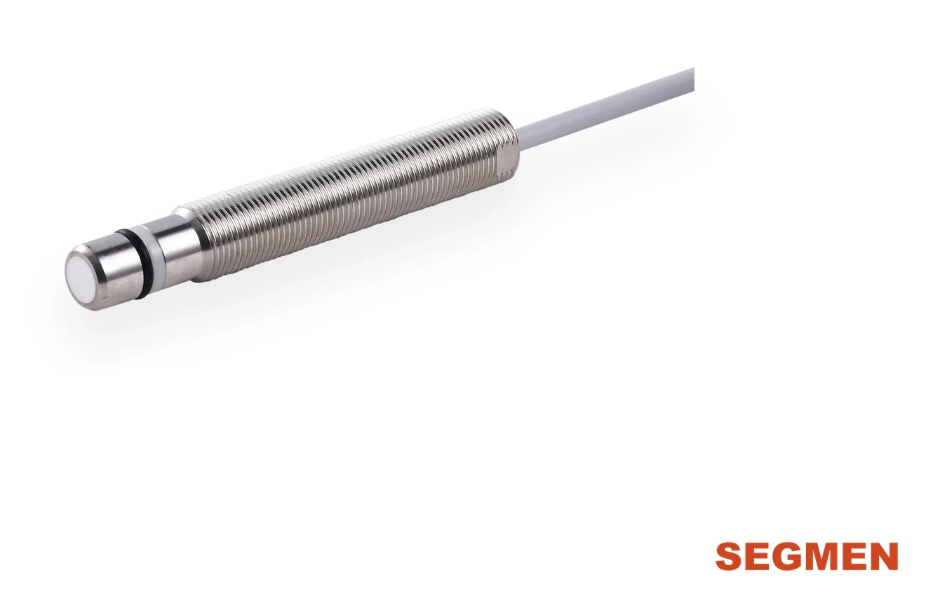
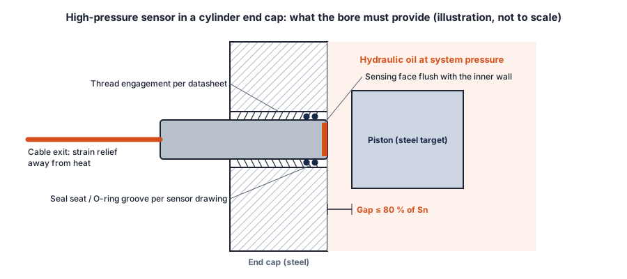
Machine the end-cap bore to the thread and seal-seat dimensions on the sensor drawing, deep enough for the housing length so the ceramic face ends flush with the inner wall. Seal on the seat or O-rings, not on the thread; tighten to the datasheet torque; check that the piston gap is within 81 % of Sn; then pressure-test the cylinder before commissioning.
Product series: SEGMENsensor high-pressure inductive proximity sensors — M8 / M12 rated 500 bar, M18 hydraulic-cylinder type up to 1000 bar. Dimension drawings are sent with the quotation.
Most field failures of pressure-rated proximity sensors are not sensor failures: they are bores that are too shallow, seals that were cut on a sharp thread edge, or a gap that was never checked. This guide walks through the installation from the drawing to the pressure test. It uses the SGI-HP series as the example, but the same steps apply to any sensor that forms part of the pressure boundary of a cylinder, pump or valve block. Always work to the dimension drawing of the exact part number; the figures below that are marked "per drawing" are not general values.
Step 1 — Start from the Sensor Drawing, Not the Thread Size
"M12" or "M18" only tells you the thread. For a pressure-tight installation you also need the thread length, the position and size of the seal seat or O-ring grooves, and the overall housing length. SGI-HP M12 models are made in housing lengths from 43 mm to 138 mm, and the length is the last part of the part number (for example L69 = 69 mm). The M18 hydraulic-cylinder type carries two O-rings on the sensing head. Request the dimension drawing for the exact part number before the end cap is machined.
SGI-HP M8 / M12: installation hole drawing
For the 500 bar M8 and M12 models we publish drawing SGM-HP-INST-002 (A3, dimensions in mm, labels in Chinese). It is built on the sensor outline: the M8 has a Ø6.5 mm pilot with the O-ring 4.5 mm behind the sensing face and 12 mm from face to thread; the M12 has a Ø10 e7 pilot with the O-ring 7.4 mm behind the face and 18 mm from face to thread. The hole gets an H8 seal bore for a clearance fit on the pilot (Ø6.5 / Ø10), an M8×1-6H or M12×1-6H thread, a 20° O-ring lead-in chamfer and a spot face for the lock nut. Minimum wall thickness from spot face to cylinder bore is 20 mm for M8 and 28 mm for M12. Screw the sensor in until the face is flush with the bore (up to 0.3 mm recessed, never protruding), then tighten the lock nut. The drawing applies to all SGI-HP M8 and M12 models.
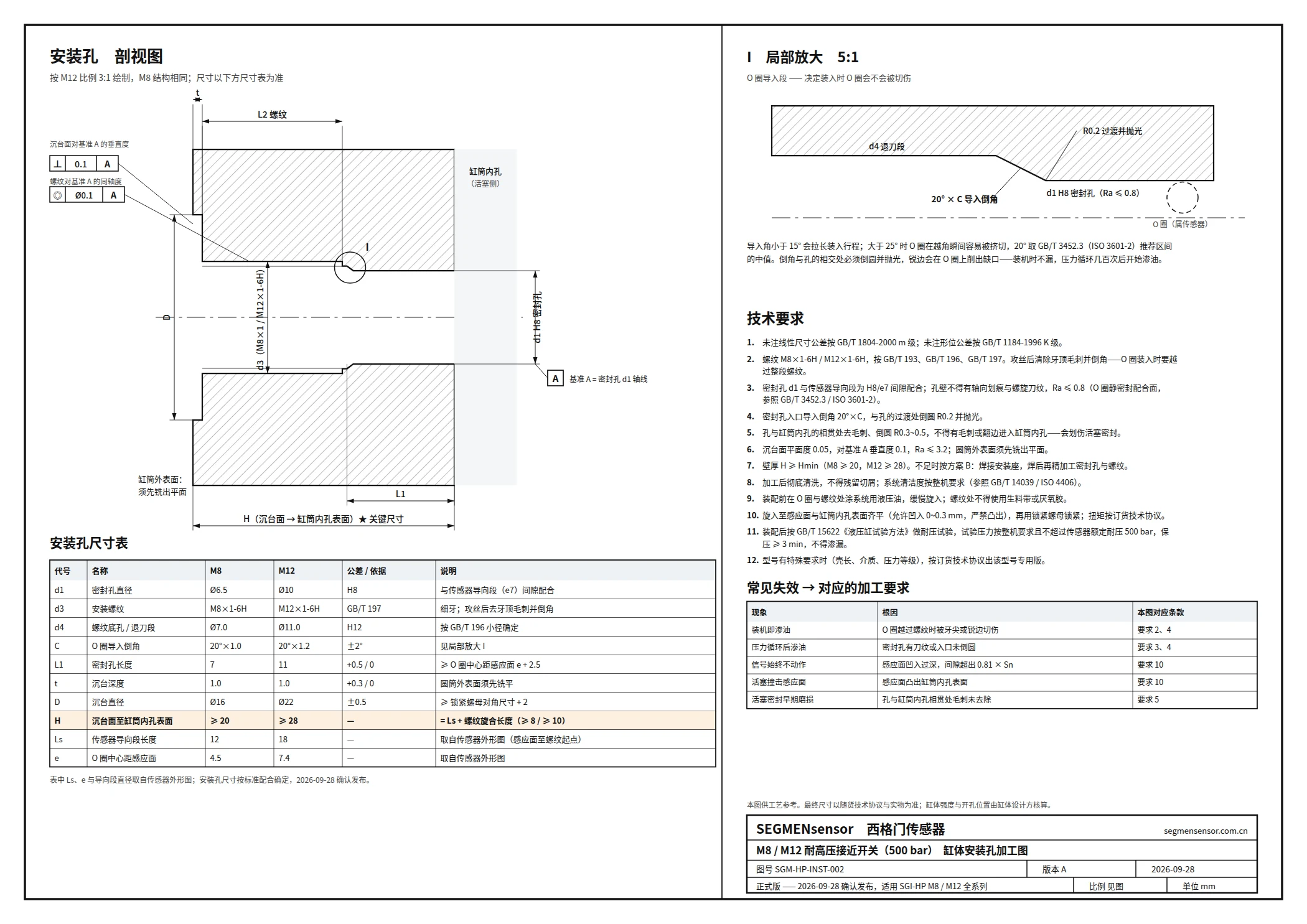
Download drawing SGM-HP-INST-002 (PDF)
M18 hydraulic-cylinder type: installation hole drawing
For the M18 hydraulic-cylinder type we publish a general installation hole drawing, SGM-M18HP-INST-001 (A3, dimensions in mm, labels in Chinese). It gives the M18×1-6H thread, the Ø16 H8 seal bore and the Ø28 spot face with tolerances, a 5:1 detail of the 20° × 1.4 O-ring lead-in chamfer, and twelve machining requirements. The key dimension is H, from the spot face to the cylinder bore surface, which equals the sensor installation length Ls (+0.3 / 0 mm): the sensing face may sit up to 0.3 mm below the bore surface and must never protrude. The seal bore diameter and installation length are confirmed per part number; send us the model and we issue the model-specific version.
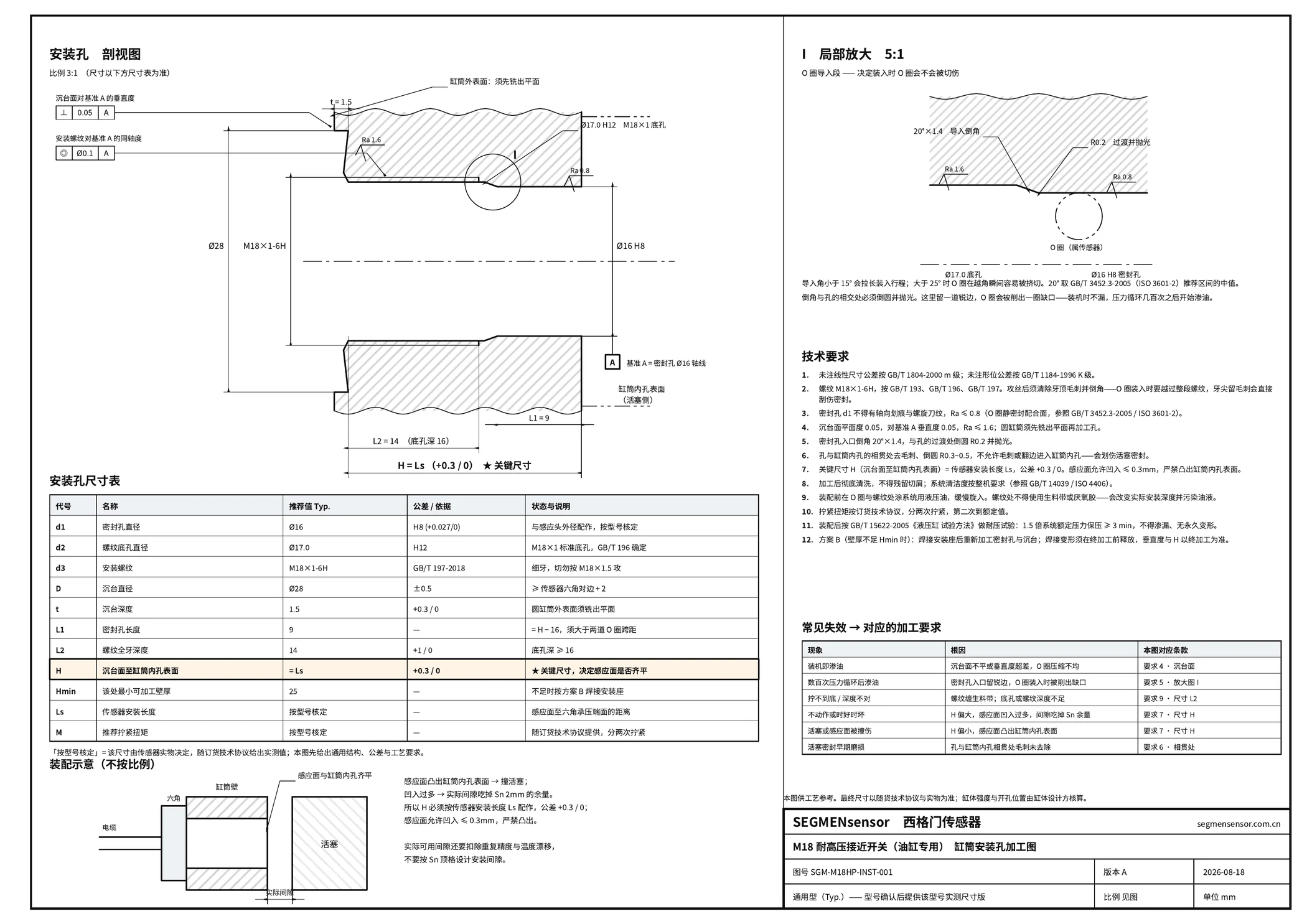
Download drawing SGM-M18HP-INST-001 (PDF, 1 MB)
Step 2 — Machine the Bore
- Thread. Cut the thread to the metric size and tolerance on the drawing. Chamfer the entry and remove burrs; a sharp thread edge is the most common cause of a cut O-ring.
- Seal seat. Machine the spot face, counterbore or O-ring bore exactly as drawn. The surface finish of the sealing face matters: a tool mark across the seal path becomes a leak path at pressure.
- Depth. The bore depth and the housing length must match so that the sensing face ends flush with the inner wall of the chamber when the sensor is fully seated. A face that stands proud can be hit by the piston; a face that is deeply recessed loses sensing distance and traps debris.
- Surroundings. SGI-HP sensors are flush types, so steel around the face is expected. Keep other moving steel parts out of the sensing field.
Hydraulic port geometry with O-ring sealing on metric threads is standardised in ISO 6149-1 — Hydraulic ports with ISO 261 metric threads and O-ring sealing ↗. Use it as a reference for seal-seat design practice, but always follow the sensor drawing: a sensor seal seat is not automatically an ISO 6149 port.
Step 3 — Clean, Inspect and Lubricate
- Flush chips and cutting fluid from the bore and the chamber. Metal chips near the face change the switching point; chips in the oil damage seals and valves.
- Inspect the O-rings or seal for damage and check that the seal material is compatible with your fluid (mineral oil, water-glycol or ester). Tell us the fluid with the enquiry.
- Lightly lubricate the seals with the system fluid before insertion so they are not twisted or cut as they pass the thread.
Get the Dimension Drawing for Your Sensor
Tell us the housing size, pressure and fluid. We send the dimension drawing and the matching part number within 24 hours. MOQ 1 piece.
Step 4 — Fit and Tighten
Screw the sensor in by hand until it seats, then tighten to the torque given on the datasheet for the housing size. Do not use thread sealant tape on a sensor that seals on a seat or O-ring: it prevents correct seating and fragments can enter the oil. Do not tighten by the cable or the connector. On connector versions, fit the M12 cable after the sensor is tightened so the cable is not twisted.
Step 5 — Check the Switching Gap
With the piston at the end position, the gap to the sensing face must be within the assured operating distance, which IEC 60947-5-2 — Proximity switches ↗ sets at 0 to 81 % of the rated distance Sn:
| Model | Rated distance Sn | Maximum gap (≈ 0.81 × Sn) |
|---|---|---|
| SGI-HP M8 | 1 mm | ≈ 0.8 mm |
| SGI-HP M12 | 1.5 mm | ≈ 1.2 mm |
| M18 hydraulic-cylinder type | 2 mm | ≈ 1.6 mm |
Include cushioning travel and the tolerance stack of piston, rod and end cap. Before filling the cylinder, move the piston to the end position and check that the LED switches; move it away and check that it resets.
Step 6 — Route and Protect the Cable
Clamp the cable close to the sensor so that vibration is not carried to the cable exit, and keep it away from hot surfaces and sharp edges. M8 and M12 models have a 2 m oil-resistant PVC cable or an M12 connector; the M18 type has a 2 m orange oil-resistant PUR cable with a detachable M12 plug. Wire the output as described in NPN vs PNP proximity sensor wiring.
Step 7 — Pressure-Test and Commission
Pressure-test the assembled cylinder according to your cylinder test procedure and check the sensor seat for weeping. Do not exceed the pressure rating of the sensor: 500 bar for M8 and M12 SGI-HP models, or the ordered grade (250, 350, 500, 800 or 1000 bar) for the M18 type. Before any later removal of a sensor, relieve the pressure and follow the lockout/tagout procedure in OSHA 29 CFR 1910.147 — The control of hazardous energy (lockout/tagout) ↗; a sensor unscrewed from a pressurised chamber becomes a projectile.
Common Installation Mistakes
| Symptom | Likely cause | Fix |
|---|---|---|
| Oil weeping at the sensor | O-ring cut on thread, damaged seal face, tape on thread | Deburr, replace seal, remove tape, check seat finish |
| Output never switches | Gap larger than 0.81 × Sn, face recessed, non-ferrous sleeve | Check bore depth and housing length, re-measure gap |
| Output always on | Face protruding into steel, chips on the face | Correct depth, clean the bore |
| Sensor pushed out or cracked face | Peak pressure above the rating | Select a higher M18 pressure grade |
Frequently Asked Questions
No, not when the sensor seals on a seat or O-rings. Tape or paste prevents correct seating and can contaminate the oil. Seal as shown on the dimension drawing.
Deep enough that the sensing face ends flush with the inner wall of the chamber when the sensor is fully seated. SGI-HP M12 models come in housing lengths from 43 mm to 138 mm, so choose the length that matches the end-cap wall.
No more than about 81 % of the rated sensing distance: roughly 0.8 mm for M8, 1.2 mm for M12 and 1.6 mm for the M18 type, including cushioning and tolerances.
It has two O-rings on the sensing head. Machine the bore to installation hole drawing SGM-M18HP-INST-001, which can be downloaded as a PDF from this article; the model-specific version is issued with the quotation.
No. Relieve the pressure, lock out the energy source and then remove the sensor.
MOQ is 1 piece. Sample and production lead times are confirmed with your quotation, and every enquiry receives a written reply within 24 hours.
Related reading: Choosing a pressure-rated sensor for cylinder end position · High-pressure inductive proximity sensors · Proximity sensor sensing distance explained · NPN vs PNP wiring
Last updated: 28 September 2026. Specifications reflect the SEGMENsensor product pages at the date of publication; datasheets and dimension drawings are sent on request.