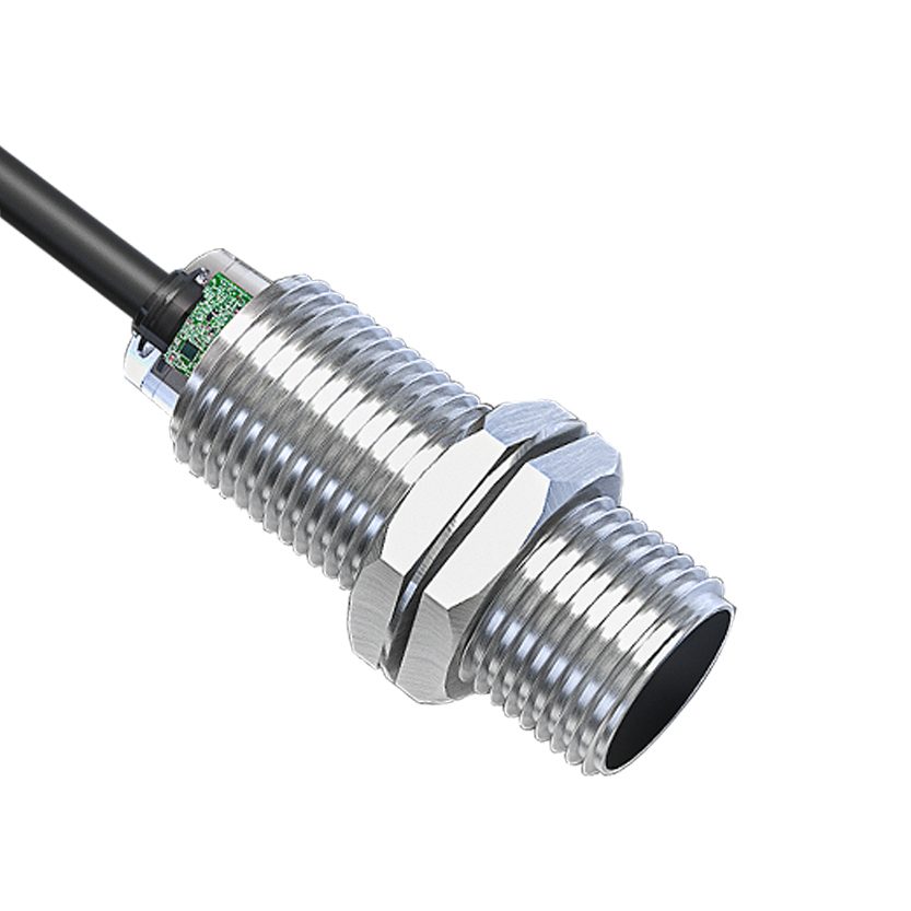
A hydraulic cylinder end-of-stroke sensor mounted in the end cap sits inside the pressurised oil chamber, so it must be a high-pressure inductive proximity sensor with a sealed metal sensing face and pressure-tight thread. SEGMENsensor supplies M12 and M18 high-pressure sensors with NPN or PNP output from 10 pieces; the pressure rating is confirmed per series on request.
Design engineers who ask us for a "proximity sensor for a hydraulic cylinder" usually need one of two things: a switching signal that confirms the piston has reached the retracted or extended end of stroke, or continuous position feedback along the whole stroke. This guide covers the first case. It explains where the sensor sits, why a standard inductive sensor fails there, how to choose the thread size, pressure rating and output in three steps, and what to send us for a quotation. For continuous feedback, see the magnetostrictive position sensor for hydraulic cylinders; the two sensors are often ordered together for the same machine.
Why a Standard Proximity Sensor Fails in a Cylinder End Cap
Inductive proximity sensors are the natural choice for end-of-stroke detection because the piston is a steel target, the sensor has no moving parts and it switches at the same point for millions of cycles. The problem is the location. The shortest and most reliable way to detect the piston is to screw the sensor through the end cap so that its sensing face looks into the chamber. That makes the sensor part of the pressure boundary of the cylinder, and a standard sensor is not designed for that duty:
- The sensing face is plastic. A standard sensor has a PBT face that is only rated for the ambient environment. Under hydraulic oil at system pressure it deforms, creeps or is pushed back into the coil, shifting the switch point or destroying the oscillator.
- There is no pressure seal. The thread of a standard sensor is designed for a bracket, not for sealing oil. Without a seal seat and a pressure-rated housing, oil escapes along the thread or through the cable gland.
- Pressure spikes exceed the nominal figure. Cushioning, valve closing and load reversals generate short peaks well above the nominal system pressure. A sensor that survives the nominal pressure in a bench test can still fail on the machine.
- Oil temperature adds to the load. Hydraulic oil in a working press or mobile machine runs hot, so the sensor sees pressure and temperature together; both have to be covered by the rating.
A high-pressure inductive proximity sensor solves this by moving the coil behind a thin stainless-steel sensing face, sealing the housing against the end-cap seat, and rating the whole assembly for the pressure chamber. Electrically it stays an ordinary 3-wire DC proximity switch, so the PLC side does not change. The alternative, an external sensor detecting a collar or cam on the piston rod, keeps the sensor out of the oil but needs extra machining, a bracket and a guard, and the switch point moves whenever the collar is disturbed. For most OEM cylinders the end-cap sensor is the cleaner design.
How End-of-Stroke Detection Works in the End Cap
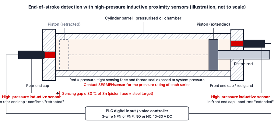
The illustration below shows the arrangement we quote most often: one high-pressure sensor in the rear end cap to confirm "retracted", and one in the front end cap, beside the rod gland, to confirm "extended". Each sensor is screwed in until its face is flush with, or slightly recessed from, the inner surface of the cap. When the piston reaches the end of stroke its steel face enters the sensing field and the output switches. The signal goes to a PLC digital input or directly to the valve controller to end the stroke, start the next sequence step or release an interlock.
Three details decide whether this works reliably on the machine:
- The gap at end of stroke. Set the distance between piston face and sensing face at no more than about 80% of the nominal sensing distance Sn on steel, allowing for cushioning travel and the tolerance stack of piston, rod and cap. How Sn, the real operating distance and the material factor relate is explained in proximity sensor sensing distance explained.
- Flush mounting in steel. The sensor is surrounded by the steel end cap, so it must be the shielded (flush) type. An unshielded sensor would be damped by the cap and stay permanently on.
- Piston material and cushioning sleeve. The target must be ferrous steel for the nominal distance to apply. If the piston carries a bronze or aluminium cushioning sleeve on the face, tell us; the sensing distance on non-ferrous metal is shorter and the sensor position or model changes accordingly.
Three-Step Selection Method
Step 1 — Fix the working conditions
Write down the nominal system pressure and the expected peak pressure, the fluid (mineral hydraulic oil, water-glycol, biodegradable ester), the oil temperature range, the cylinder duty (cycles per minute, continuous or intermittent) and the environment around the end cap: outdoor, wash-down, weld spatter or vibration. These decide the series and the seal, and they are the first thing our engineers check before quoting.
Step 2 — Choose thread size and pressure rating
The end cap decides the thread. M12 × 1 is used where the cap is thin or the space around the rod gland is tight and a 4 mm shielded sensing distance is enough. M18 × 1 gives an 8 mm shielded sensing distance, more margin for cushioning travel and a longer thread engagement for the seal. The pressure rating of SEGMENsensor high-pressure sensors depends on the series, the thread size and the seal design, so we do not publish one figure for all models: contact us for the pressure rating of the model that matches your nominal and peak pressure. For a thermal margin above the standard ambient range, ask for the high-temperature series, which is rated by grade (max. +T °C) rather than as a single specification.
Step 3 — Choose the output and the connection
Choose PNP (sourcing) or NPN (sinking) to match the PLC input card, and normally open or normally closed to suit the fail-safe logic; typical wiring is shown in NPN vs PNP proximity sensor wiring. Then specify the termination: a fixed cable with oil-resistant PUR jacket for a cylinder that is wired once, or an M12 connector where the cylinder is removed for service. The sensor otherwise behaves like the SE2 series described in our inductive proximity sensor manufacturer and OEM guide.
Standard vs High-Pressure Inductive Proximity Sensor
| Feature | Standard SE2 inductive sensor | High-pressure inductive sensor (SGI-HP) |
|---|---|---|
| Mounting position | Bracket, tie rod or machine frame, outside the fluid | Screwed through the cylinder end cap, sensing face inside the pressure chamber |
| Sensing face | PBT plastic | Stainless steel, one piece with the housing |
| Thread and seal | Metric thread for clamping nuts, no pressure seal | Metric thread with seal seat for the end-cap bore, pressure-tight |
| Pressure rating | Not rated for pressure | Contact us for pressure rating (per series and thread size) |
| Target | Any ferrous metal part; reduction factor for non-ferrous | Piston face (steel); tell us about non-ferrous cushioning sleeves |
| Electrical interface | 3-wire DC, NPN/PNP, NO/NC, 10–30 V DC | Same: 3-wire DC, NPN/PNP, NO/NC, 10–30 V DC |
| Typical use | Conveyors, machine tools, packaging, cylinder rod collars | Hydraulic cylinder end-of-stroke, press and clamp confirmation, hydraulic valve blocks |
Specification Table: M12 and M18 High-Pressure Sensors
The electrical and sensing figures below are those of the SEGMENsensor inductive proximity sensor product page for the M12 and M18 shielded sizes, which the high-pressure series shares; the M18 inductive proximity sensor page has the drawing and thread dimensions. Housing, sealing and pressure figures for the SGI-HP series are confirmed by our engineers for each enquiry.
| Parameter | M12 × 1, shielded | M18 × 1, shielded |
|---|---|---|
| Nominal sensing distance Sn | 4 mm | 8 mm |
| Repeatability | ≤ 5% Sn | ≤ 5% Sn |
| Switching frequency | 1,500 Hz | 1,000 Hz |
| Supply voltage | 10–30 V DC, 3-wire | |
| Output | NPN or PNP, NO or NC (specify when ordering); output current 200 mA; voltage drop ≤ 2.5 V | |
| Operating temperature | −25 °C to +70 °C standard; high-temperature series rated by grade, max. +T °C | |
| Housing / sensing face | 316L stainless steel housing with stainless sensing face on the high-pressure series; brass or zinc alloy on the standard series | |
| Pressure rating | Contact us for pressure rating — state nominal and peak system pressure and the fluid | |
| Cable / connection | 2 m cable standard, oil-resistant PUR on request, 0.5–10 m custom length, or M12 4-pin plug | |
| Protection rating | IP67 standard; IP68 on request (housing side, per IEC 60529) | |
| Certifications | CE, RoHS; built to IEC 60947-5-2 in an ISO 9001:2015 certified factory | |
| OEM MOQ / lead time | 10 pcs · samples (1–5 pcs) in 5–7 days · production in 3–5 weeks · reply within 24 hours | |
The definitions of nominal sensing distance, shielded and unshielded mounting and switching frequency follow IEC 60947-5-2 — Low-voltage switchgear and controlgear, Part 5-2: Control circuit devices and switching elements — Proximity switches ↗. The IP67 and IP68 figures describe the housing and connector side of the sensor per IEC 60529 — Degrees of protection provided by enclosures (IP Code) ↗; they are not a pressure rating, which is a separate figure confirmed per model.
Download the one-page datasheet (PDF)
The inductive proximity sensor datasheet lists every size with sensing distance, switching frequency, output options, housing materials, dimensions, wiring colour codes and the ordering code. Ask our engineers for the high-pressure series supplement with the pressure rating for your thread size. No registration required.
Need a high-pressure proximity sensor specified for your cylinder?
Send nominal and peak pressure, thread size, output type and quantity to our engineers. MOQ 10 pcs · samples in 5–7 days · reply within 24 hours.
Where End-of-Stroke Sensors Are Specified
Hydraulic presses and clamping units. The press controller must know that the ram is fully open before the operator or a robot loads the next blank, and that the clamp cylinder is fully closed before the working stroke starts. An end-cap sensor gives that confirmation without an external cam that can be knocked out of position. The same signal supports the energy-control procedures that OSHA 29 CFR 1910.147 — The control of hazardous energy (lockout/tagout) ↗ requires before servicing hydraulic equipment, because the machine state is verified by a sensor rather than assumed.
Injection moulding and die-casting machines. Mould-close, ejector-back and core-pull cylinders are sequenced on end-of-stroke signals. Sensors in the end caps replace external limit switches that drift with heat and vibration, and the M12 connector version lets the cylinder be exchanged without rewiring.
Mobile and agricultural hydraulics. Boom, outrigger and steering cylinders on construction, forestry and farm machines use retracted and extended confirmation for interlocks and automatic sequences. Here the oil-resistant PUR cable, the stainless housing and the pressure spikes from load reversal all matter; specify the peak pressure, not just the relief-valve setting.
Steel mill, forging and heavy-duty cylinders. Descaling, tilting and manipulator cylinders operate hot, dirty and continuously. End-cap sensors are protected by the cap itself and, with a high-temperature series where needed, keep the switch point stable over long campaigns.
Marine, offshore and water-treatment gates. Sluice-gate, hatch and winch cylinders in wet environments benefit from the sealed stainless design; ask for IP68 on the connector side when the end cap is regularly submerged or washed down.
When You Need Continuous Position Instead
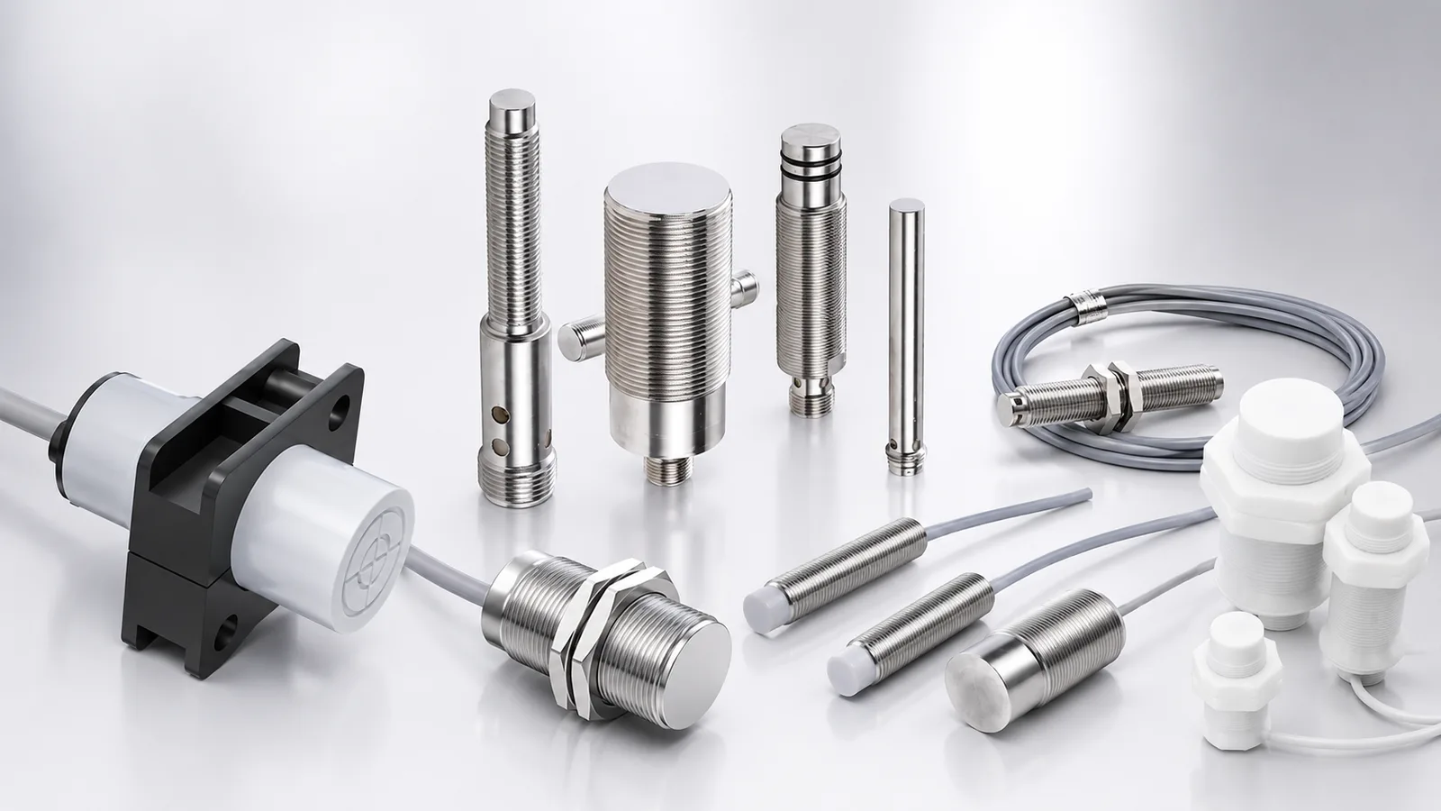
An end-of-stroke sensor answers "is the piston at the end?" It cannot tell the controller where the piston is in between. If the application needs position control, synchronisation of several cylinders or stroke logging, use the magnetostrictive position sensor for hydraulic cylinders, which is built into the piston rod and gives absolute position over the whole stroke with SSI or 4-20 mA output. Many OEM cylinders carry both: the magnetostrictive sensor for control and one or two high-pressure proximity sensors as independent end-position confirmation for the safety logic. The inductive proximity sensor product page lists the standard, high-temperature and all-metal series that share the same output options.
The Six Parameters to Send for a Quote
- Pressure: nominal system pressure and expected peak pressure, and whether the sensor sees the full stroke pressure or only the cushioning chamber.
- Fluid and temperature: mineral oil, water-glycol or ester; oil temperature range and ambient temperature at the end cap.
- Thread and space: M12 × 1 or M18 × 1, end-cap wall thickness, thread depth available, position relative to the rod gland.
- Target and gap: piston material, cushioning sleeve material if any, and the gap between piston face and sensing face at end of stroke including tolerances.
- Output and connection: NPN or PNP; NO or NC; supply voltage; fixed cable (length, PUR) or M12 4-pin connector.
- Quantity: sample count now, expected annual volume, destination and Incoterm (EXW, FOB Shenzhen, CIF, DDP), plus private-label requirements if any.
OEM Supply: MOQ, Samples and Lead Time
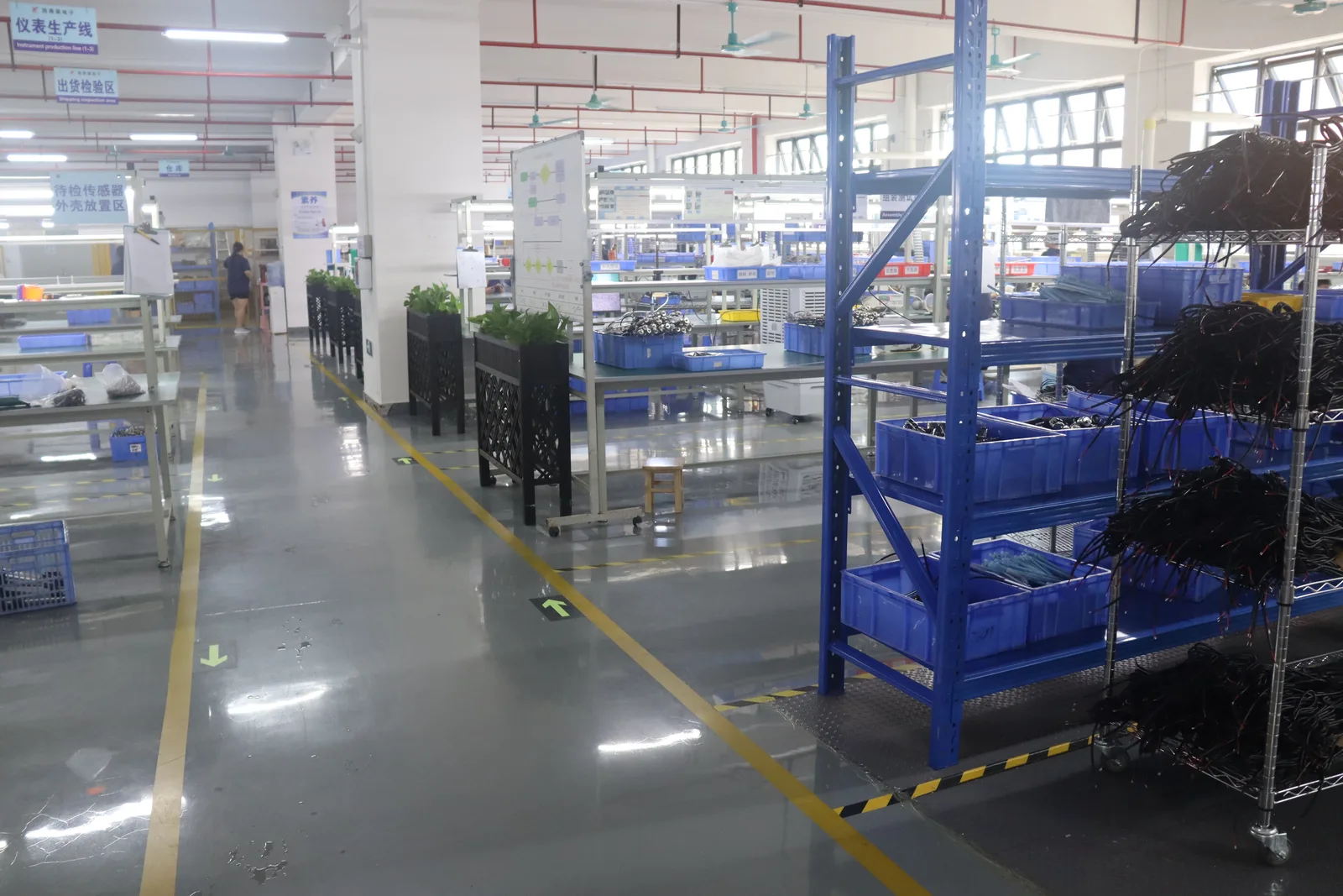
Segmen Industrial Development Co., Ltd. was founded in Shenzhen in 2019. Its engineering team brings more than 20 years of sensor experience and supplies 200+ OEM customers in 30+ countries. High-pressure proximity sensors are built to order on an ISO 9001:2015 certified line, so the sample that is qualified in your cylinder is the same configuration that ships in the series order.
| Term | SEGMENsensor standard |
|---|---|
| Minimum order quantity | 10 pieces per configuration |
| Samples | 1–5 pieces, shipped in 5–7 days |
| Production lead time | 3–5 weeks after order confirmation |
| Enquiry response | Within 24 hours, with a written quotation and the pressure rating for the selected model |
| Tooling-free customisation | Cable length and jacket, connector type, output type (NPN/PNP, NO/NC) |
| Documentation | CE and RoHS documents, datasheet, wiring diagram; private-label packaging and manuals for OEM customers |
Frequently Asked Questions
It is an inductive proximity switch whose sensing face, housing and thread seal are built to sit inside a pressurised hydraulic chamber, typically screwed into a cylinder end cap. It detects the steel piston at the end of stroke without any contact, and outputs a standard NPN or PNP switching signal. A standard proximity sensor has a plastic sensing face and no pressure seal and is not designed for this duty.
The rating depends on the series, thread size and seal design, so we do not publish a single figure. Send the nominal and peak system pressure, the thread size and the fluid to info@segmensensor.com and our engineers will confirm the pressure rating for the matching SGI-HP model within 24 hours.
Use M12 where the end cap is thin or the bore is small and a 4 mm shielded sensing distance is enough. Use M18 where the cap can take a longer thread and you need the 8 mm shielded sensing distance to allow for piston cushioning and mechanical tolerance. Both are supplied as NPN or PNP, NO or NC, with cable or M12 connector.
Only if the sensor is mounted outside the pressure chamber, for example on a collar or cam on the piston rod. Inside the end cap, system pressure and pressure spikes act directly on the sensing face and seal, so a standard sensor will leak or fail. Use a high-pressure series for any sensor that is part of the pressure boundary.
Exactly like a standard 3-wire DC proximity sensor: brown to +10–30 V DC, blue to 0 V, black to the PLC digital input. Choose PNP (sourcing) for inputs that expect a positive signal and NPN (sinking) for inputs that expect a switched 0 V. Normally-closed versions are available for fail-safe logic.
MOQ is 10 pieces per configuration. Samples of 1–5 pieces ship in 5–7 days, production orders in 3–5 weeks, and every enquiry receives a written reply within 24 hours.
Related reading: Inductive proximity sensors — product page · M18 inductive proximity sensor · Magnetostrictive sensor for hydraulic cylinders · Proximity sensor sensing distance explained · NPN vs PNP proximity sensor wiring
Last updated: 28 September 2026. Electrical and sensing specifications reflect the SEGMENsensor product page at the date of publication; pressure ratings are confirmed per model on request.