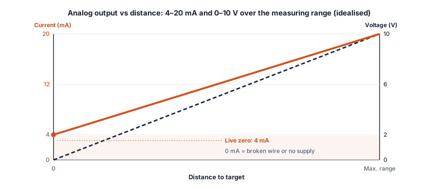
Use 4–20 mA for long cable runs, noisy plants and wherever a broken wire must be detected, because the signal never drops to zero in normal operation. Use 0–10 V for short runs to a voltage input. If you are not sure which input the controller has, a dual-output sensor gives 0–10 V and 0–20 mA at the same time.
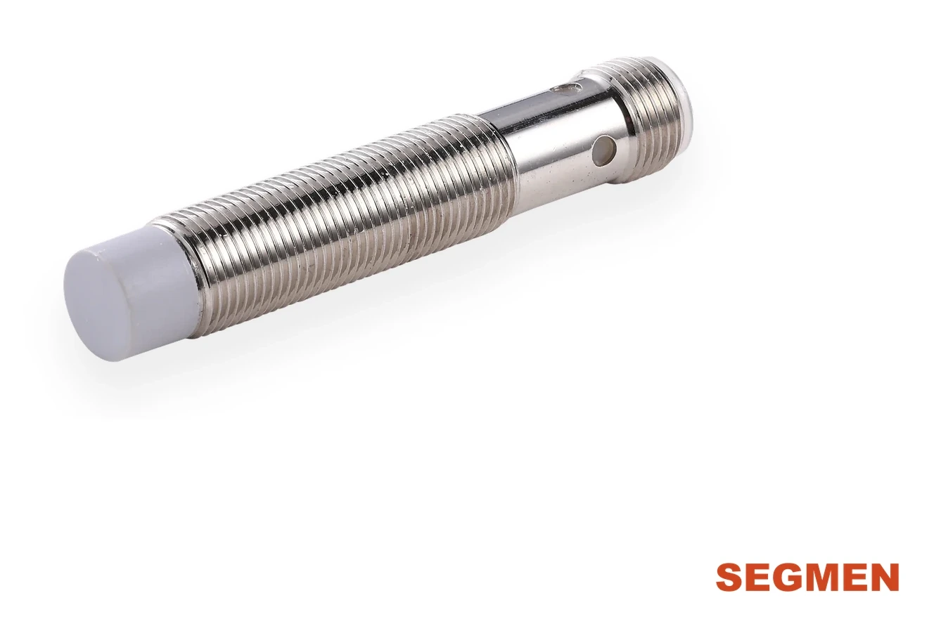
Product series: SEGMENsensor analog inductive proximity sensors — 4–20 mA, 0–10 V or dual output, measuring ranges up to 10 mm, 0.02 mm repeatability, D6.5 / M8 / M12.
An analog proximity sensor measures the gap to a metal target and outputs it as a continuous signal instead of switching on or off. Choosing the signal is the first decision after the measuring range, and it decides how far the cable can run, how the controller detects a fault and how the input must be wired. This guide compares 4–20 mA and 0–10 V for analog inductive sensors, explains the dual-output option, and shows how to scale and check the signal.
What Is the Difference Between 4–20 mA and 0–10 V?
A 4–20 mA signal represents the measured gap as a current. Because the same current flows through the whole loop, the cable resistance does not change the value the controller reads, as long as the total load stays within the sensor limit. The standard ranges are set out in IEC 60381-1 — Analogue signals for process control systems, direct current signals ↗. A 0–10 V signal represents the gap as a voltage. It is simple to wire and read, but any voltage drop and interference picked up on the cable adds directly to the reading; voltage signals are covered by IEC 60381-2 — Analogue signals for process control systems, direct voltage signals ↗.
Side-by-Side Comparison
| 4–20 mA (current) | 0–10 V (voltage) | |
|---|---|---|
| Effect of cable length | Low, within the load limit | Voltage drop and pickup add to the reading |
| Noise immunity | Higher | Lower; keep runs short and shielded |
| Broken-wire detection | Yes: live zero at 4 mA, a broken wire reads 0 mA | No: 0 V can be a real reading or a fault |
| Load limit (SGI-AO) | ≤ 400 Ω | ≥ 2 kΩ |
| Typical input | PLC current input, process controllers | PLC voltage input, drives, panel meters |
| Best for | Long runs, noisy plants, safety-relevant monitoring | Short runs inside a machine or cabinet |
Why Use 4–20 mA Instead of 0–10 V?
- Live zero. The minimum of the range is 4 mA, not zero, so a reading below about 4 mA means a fault — broken wire, loose terminal or no supply — rather than a target at one end of the range.
- Cable resistance does not matter within the load limit. A current source pushes the same current through the loop; the controller input sees the correct value whether the cable is 2 m or much longer, provided the sum of cable and input resistance stays within the ≤ 400 Ω load of the SGI-AO sensor.
- Better noise immunity. The low input resistance of a current input makes it less sensitive to voltages induced by drives, motors and welding equipment.
The disadvantages are small: a current input costs slightly more, loop resistance must be checked, and a 4–20 mA signal cannot be read with a plain voltmeter without a shunt resistor.
Choose the Right Analog Output
Tell us the measuring range, target material and controller input. We recommend the housing and output code within 24 hours. MOQ 1 piece.
When to Choose the Dual-Output Version
SEGMENsensor dual-output (M) models provide 0–10 V and 0–20 mA at the same time, with 0–10 V into ≥ 2 kΩ and 0–20 mA into ≤ 400 Ω. One part number therefore covers both input types, which helps when the same machine is built with different controllers, or when a local display reads the voltage while the PLC reads the current. Note that the current output of the dual models is 0–20 mA, not 4–20 mA: it has no live zero, so if you need wire-break detection choose the 4–20 mA (I) model.
| Code in part number | Output | Example |
|---|---|---|
| I | 4–20 mA | SGI-AO12S-040I-Q4 |
| V | 0–10 V | SGI-AO12S-040V-Q4 |
| M | 0–10 V + 0–20 mA | SGI-AO12S-040M-Q4 |
Wiring an Analog Proximity Sensor
- Supply 18–30 V DC; analog sensors need a higher minimum supply than many switching sensors, so check the supply at the sensor end of long cables.
- Connect the signal to an input configured for the same signal type. A 4–20 mA sensor on an input set to voltage, or the reverse, gives a fixed or meaningless reading.
- Keep the total load within the limits: ≤ 400 Ω for current, ≥ 2 kΩ for voltage.
- Use shielded cable for analog signals, route it away from motor and drive cables, and ground the shield at one end.
- Follow the wiring diagram on the datasheet of your part number; dual-output models have an additional conductor.
For troubleshooting current loops in general, see 4-20 mA wiring for pressure transmitters; the loop rules are the same.
Scaling the Signal and Converting Between Types
In the PLC, scale the raw signal to distance. For a 4–20 mA sensor with a linear range from dmin to dmax:
distance = dmin + (I − 4 mA) ÷ 16 mA × (dmax − dmin)
For 0–10 V use distance = dmin + U ÷ 10 V × (dmax − dmin). Because linearity is better than 5 % rather than perfect, calibrate on the real target: record the signal at both ends of the travel (and a few points between if accuracy matters) and use those values. Repeatability of 0.02 mm means the sensor returns the same value for the same gap, so a calibration table holds.
Converting 4–20 mA to a voltage: a precision resistor across a voltage input turns current into voltage (U = I × R). A 500 Ω resistor gives 2–10 V, a 250 Ω resistor 1–5 V. Check that the resistor plus cable stays within the ≤ 400 Ω load of the sensor — 500 Ω does not, so use 250 Ω, or choose a 0–10 V or dual-output model instead.
Checking the Signal on Site
| Reading | Meaning | Check |
|---|---|---|
| 0 mA on a 4–20 mA sensor | Broken wire, loose terminal or no supply | Supply voltage at the sensor, terminals, cable |
| Fixed at one end of the range | Target outside the measuring range, or wrong input type | Gap, sensor position, input configuration |
| Reading jumps or drifts | Noise pickup, shield not grounded, target vibrating | Cable routing, shield, mechanical stability |
| Range smaller than expected | Non-ferrous target | Calibrate on the real target; aluminium and brass give a shorter range than steel |
Frequently Asked Questions
Because a 4-20 mA signal is not affected by cable resistance within the load limit, is less sensitive to noise, and its 4 mA live zero lets the controller detect a broken wire.
There is no single figure: it depends on cable resistance, input resistance and noise in the plant. Keep 0-10 V runs short and shielded, and use 4-20 mA for long runs.
Place a precision resistor across a voltage input: 250 Ω gives 1-5 V. Keep the total load within the 400 Ω limit of the SGI-AO current output.
SEGMENsensor M models provide 0-10 V and 0-20 mA at the same time, so one part number serves both input types. For wire-break detection choose the 4-20 mA (I) model.
The loop resistance must stay within the sensor load limit, current inputs cost slightly more, and the signal cannot be read directly with a voltmeter.
Any metal, including steel, stainless steel, brass and aluminium. The ranges refer to steel; non-ferrous metals give a shorter range, so calibrate on the real target.
MOQ is 1 piece. Sample and production lead times are confirmed with your quotation, and every enquiry receives a written reply within 24 hours.
Related reading: Analog inductive proximity sensors · 4-20 mA loop wiring · Proximity sensor sensing distance explained · Special-environment proximity sensors
Last updated: 28 September 2026. Specifications reflect the SEGMENsensor product pages at the date of publication; datasheets and dimension drawings are sent on request.