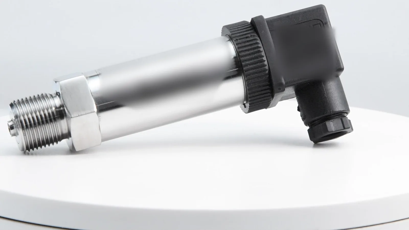
2-wire transmitters are loop-powered: the same two conductors carry the supply and the 4–20 mA signal, which keeps cabling simple and is the default for pressure and level transmitters. 3-wire transmitters add a dedicated supply wire and use a shared 0 V, so they can power heavier electronics and output 0–10 V. 4-wire transmitters separate power and signal completely, which allows mains supply and an isolated output. Pick the one the datasheet specifies and match it to an active or passive PLC input.
How is each transmitter type wired?
The diagram shows the three arrangements side by side. What changes is where the power comes from and which conductor the signal current returns on.
2-wire (loop-powered)
The supply, the transmitter and the receiver resistor are connected in series. The transmitter acts as a current regulator: it lets 4 mA through at 0% of range and 20 mA at 100%, and it runs its own electronics from the part of that current below 4 mA. That is why the 4–20 mA standard starts at 4 mA rather than 0 — a live zero powers the device and makes a broken wire (0 mA) obvious. The IEC 60381-1 standard for direct-current analogue signals ↗ defines the 4–20 mA range used by these loops.
3-wire
A third conductor brings dedicated supply power, so the transmitter is not limited to the energy available below 4 mA. The output can be a current (4–20 mA) or a voltage (0–10 V, 0–5 V, 0.5–4.5 V), and its return runs through the shared 0 V conductor. Because the 0 V is common to power and signal, a voltage drop on that wire shifts a voltage signal, and the output is not isolated from the supply.
4-wire
Power and signal have their own pairs. The supply can be 24 V DC or mains AC, and the transmitter generates (sources) the 4–20 mA itself — an active output. This suits instruments that need more power than a loop can supply, such as analysers or transmitters with relays and large displays, and it allows galvanic isolation between supply and output. Voltage outputs from 3-wire and 4-wire devices are covered by IEC 60381-2 on direct-voltage analogue signals ↗.
2-wire vs 3-wire vs 4-wire: comparison table
| Feature | 2-wire | 3-wire | 4-wire |
|---|---|---|---|
| Conductors to the field | 2 | 3 | 4 |
| Power source | The 4–20 mA loop | Separate +V wire, shared 0 V | Separate power pair (DC or AC) |
| Typical output | 4–20 mA (HART possible) | 4–20 mA or 0–10 V / 0–5 V | 4–20 mA, voltage, often isolated |
| Power available to the electronics | Below 4 mA × terminal voltage | Not limited by the loop | Not limited by the loop |
| Signal isolation from supply | One loop, nothing to isolate | No — common 0 V | Possible (separate pairs) |
| PLC input type | Active input, or passive input + external supply | Passive (sink) input on the same 0 V | Passive input (transmitter is the source) |
| Main limit | Loop resistance vs supply voltage | Voltage drop on shared 0 V | Extra cabling and supply |
| Typical instruments | Pressure, level, temperature transmitters | Sensors with 0–10 V output, DC-powered displacement sensors | Flow meters, analysers, mains-powered transmitters |
How long can a 2-wire loop be? Formula and worked example
A loop-powered transmitter needs a minimum voltage at its own terminals. Everything else in the loop — the PLC input resistor, cable, barriers, isolators, indicators — consumes voltage at 20 mA. The budget is:
Rmax = (Vsupply − Vmin) / 0.020 A
- SEGMENsensor pressure transmitters are specified for 10–36 V DC, so Vmin = 10 V. With a 24 V DC supply: Rmax = (24 − 10) / 0.020 = 700 Ω.
- Subtract the PLC input resistor, typically 250 Ω: 450 Ω is left for cable and other devices.
- Copper 0.5 mm² has about 0.035 Ω per metre per conductor, so one metre of cable run (out and back) adds about 0.07 Ω — roughly 7 Ω per 100 m.
- 450 Ω ÷ 0.07 Ω/m ≈ 6,400 m of theoretical run. A safety barrier or isolator in the loop takes a large part of that budget, so add its resistance before deciding.
- For a level transmitter with a 12 V minimum (SLS: 12–36 V DC), the same supply gives (24 − 12) / 0.020 = 600 Ω.
HART communication needs at least 250 Ω in the loop for the digital signal to be read; see what HART protocol is and how it rides on 4–20 mA. Convert any current to engineering units with the 4–20 mA calculator.
Which PLC input do 2-wire, 3-wire and 4-wire transmitters need?
Exactly one device in a current loop must supply the energy. A common wiring fault is having two sources in the loop, or none.
| Transmitter | PLC input supplies 24 V (active) | PLC input unpowered (passive) |
|---|---|---|
| 2-wire (passive device) | Correct — no external supply needed | Correct — add a 24 V DC supply in series |
| 3-wire | Use the card’s passive terminals for the signal | Correct — share 0 V with the supply |
| 4-wire (active output) | Wrong — two sources; reading saturates or the channel trips | Correct |
Symptoms: a 2-wire transmitter on a passive input with no supply reads 0 mA; a 4-wire active output on an active input reads full scale, wrong or nothing. Step-by-step terminal wiring for pressure transmitters is in the 4–20 mA pressure transmitter wiring guide.
Which one should you choose?
- 2-wire when the instrument is a process transmitter with 4–20 mA output and the cable run is long; it uses the fewest conductors and suits HART and intrinsically safe loops.
- 3-wire when the input card expects a voltage (0–10 V), or the sensor electronics need more power than a loop provides and the cable is short enough for the shared 0 V.
- 4-wire when the instrument is mains-powered, needs isolation between supply and output, or drives relays, heaters or large displays.
In hazardous areas, the wiring method must also suit the protection concept; in the US, electrical equipment in classified locations falls under OSHA 29 CFR 1910.307 — Hazardous (classified) locations ↗. Do not confuse transmitter wiring with “3-wire” proximity switches: those are DC switching sensors with an NPN or PNP output, explained in the NPN vs PNP proximity sensor wiring guide. For the analog output choice itself, see 4–20 mA vs 0–10 V.
Not sure which wiring your system needs?
Tell us the PLC input type (active or passive, current or voltage), supply voltage, cable length and any barrier in the loop. We will match a transmitter output and wiring to it. MOQ 1 pc · samples in 5–7 working days · production 3–5 weeks · reply within 24 hours.
How are SEGMENsensor transmitters wired?
| SEGMENsensor product | Outputs | Supply | Wiring |
|---|---|---|---|
| 4–20 mA pressure transmitter | 4–20 mA / 0–10 V / RS485 | 10–36 V DC (loop powered) | 2-wire for 4–20 mA; voltage and RS485 versions wired per datasheet |
| SLS submersible level transmitter | 4–20 mA / 0–10 V / RS-485 Modbus | 12–36 V DC | 2-wire for 4–20 mA |
| Magnetostrictive position sensors | 2-wire 4–20 mA + HART; also 0–10 V, SSI, RS485 and more per model | 24 V DC standard; 12 V and 5 V ranges per output and model | 2-wire for 4–20 mA + HART; others per model |
| DC LVDT displacement sensors | 4–20 mA / 0–10 V / ±10 V / RS485 | 10–30 V DC (DC type) | Separate supply and signal conductors, per datasheet |
Pressure transmitters cover 0–0.1 bar to 0–400 bar at ±0.25% FS (±0.1% FS high-accuracy); all models are on the pressure sensor page. The exact wiring for each output option is confirmed on the datasheet and with the quotation. Quotations are FOB China, payment 100% T/T in advance.
Frequently Asked Questions
Yes. A 2-wire transmitter takes its operating power from the 4–20 mA loop, so the same two conductors carry power and signal. It needs a minimum voltage at its terminals, for example 10 V for a transmitter rated 10–36 V DC.
No. A voltage output needs a separate supply, so 0–10 V transmitters are 3-wire or 4-wire. If the PLC needs a voltage, a 250 Ω resistor converts a 2-wire 4–20 mA signal into 1–5 V.
Not to the loop-supply terminals. A 4-wire transmitter has an active output that already sources the current, so it must go to a passive input. Two sources in one loop make the reading saturate or trip the channel.
Use R_max = (V_supply − V_min) / 0.020 A. With a 24 V DC supply and a 10 V transmitter minimum, R_max is 700 Ω. Subtract the PLC input resistor, barriers and about 7 Ω per 100 m of 0.5 mm² cable run.
No. Both have +V, 0 V and an output wire, but a 3-wire transmitter outputs an analog value such as 4–20 mA or 0–10 V, while a 3-wire proximity sensor outputs an on/off NPN or PNP switching signal.
The 4–20 mA versions are 2-wire: pressure transmitters on 10–36 V DC and SLS submersible level transmitters on 12–36 V DC. Voltage and RS485 versions are wired per datasheet. MOQ is 1 piece, samples ship in 5–7 working days, production takes 3–5 weeks, and we reply within 24 hours.