2-wire (loop-powered): Power supply (+) → Transmitter (+), Transmitter (−) → PLC AI (+). PLC AI (−) → Power supply (−). Loop current = 4–20 mA proportional to pressure.
3-wire: Brown = +24 V supply, Blue = 0 V supply, Black/Yellow = current output to PLC AI (+). PLC AI (−) → 0 V. Use a 250 Ω burden resistor if your PLC input requires a 1–5 V voltage input.
What Is a 4-20mA Signal and Why Does It Matter?
The 4-20mA current loop is the dominant standard for industrial process measurement. Instead of transmitting a voltage (which degrades with cable length), the transmitter regulates the loop current in proportion to the measured pressure. Because current is the same everywhere in a series loop, a 100 m cable introduces no measurement error — only a voltage drop that reduces compliance headroom.
| Signal Type | Noise Immunity | Cable Length | Short Circuit Safe | Live Zero Fault Detection |
|---|---|---|---|---|
| 4-20 mA | Excellent | Up to 1,000 m | Yes (current-limited) | Yes — 0 mA = fault |
| 0-10 V | Moderate | Up to 50 m | No (requires series R) | No — 0 V is valid zero |
| 0-5 V | Moderate | Up to 30 m | No | No |
| HART (on 4-20mA) | Excellent | Up to 3,000 m | Yes | Yes + diagnostics |
The 4 mA live zero is the critical advantage: a genuine zero-pressure reading produces 4 mA, while a broken wire, dead transmitter, or shorted output produces 0 mA. Your PLC can detect the fault condition automatically — something a 0-10 V signal cannot do.
2-Wire Loop-Powered Wiring — Step by Step
A 2-wire transmitter draws its operating power from the same two wires that carry the 4-20mA signal. The transmitter, power supply, and PLC input are all in series. This is the simplest and most common configuration for process pressure transmitters.
- 1Verify transmitter polarity markings. 2-wire transmitters have a (+) terminal and a (−) terminal. The (+) is typically connected to the power supply positive; the output current exits from the (−) terminal.
- 2Connect the power supply (+) to the transmitter (+) terminal. Use shielded twisted-pair cable (0.5 mm² minimum). For runs over 100 m, use 0.75 mm² to limit resistive voltage drop.
- 3Connect the transmitter (−) terminal to the PLC analog input (+) terminal. The loop current flows through the PLC input.
- 4Connect the PLC analog input (−) or AGND terminal back to the power supply (−). This completes the series loop. All three devices — supply, transmitter, PLC — are in one continuous circuit.
- 5Check if your PLC AI card requires an external burden resistor. Many modern PLC AI cards have an internal 250 Ω resistor and accept 4-20mA directly. Older cards or voltage-mode cards require you to wire a 250 Ω resistor in parallel with the input to develop a 1-5 V signal. Check your PLC card manual.
- 6Ground the cable shield at the control panel end only. Leave the field end floating to prevent ground loops. Tape or insulate the field end of the shield.
- 7Power up and verify at 4 mA (0% pressure). Use a multimeter in series (current mode) or measure voltage across the 250 Ω burden: 1.00 V = 4 mA, 5.00 V = 20 mA. Apply known pressure and confirm proportional response.
| Step | Connection | Common mistake to avoid |
|---|---|---|
| 1 | Supply (+) → Transmitter (+) | Reversed polarity — transmitter outputs 0 mA and the PLC reports a wire break. |
| 2 | Transmitter (−) → PLC AI (+) | Landing on a voltage input with no 250 Ω burden — the loop stays open, no reading. |
| 3 | PLC AI (−) → Supply (−) | Return wire left off — the series loop is not closed, no current flows. |
| 4 | Cable shield → panel ground only | Shield grounded at both ends — ground loop, noisy or drifting value. |
| 5 | Verify 4 mA at 0 % (1.00 V across 250 Ω) | Skipping the zero check — a wrong range or polarity goes unnoticed. |
3-Wire Externally-Powered Wiring — Step by Step
A 3-wire transmitter has a dedicated power supply circuit (Brown = +Vcc, Blue = 0 V) separate from the current output wire (Black or Yellow). This allows the transmitter to draw more operating power without affecting the output signal, and is common in transmitters with displays or communication interfaces.
| Step | Connection | Common mistake to avoid |
|---|---|---|
| 1 | Supply +24 V → Transmitter V+ (Brown) | Brown and Blue swapped — transmitter does not power up. |
| 2 | Supply 0 V → Transmitter GND (Blue) and PLC AI (−) | Two different 0 V references — ground loop, reading drifts. |
| 3 | Transmitter OUT (Black) → PLC AI (+) | Output landed on a voltage input without a 250 Ω burden — no reading. |
| 4 | Cable shield → panel ground only | Shield grounded at both ends — ground loop and noise. |
- The transmitter GND (Blue) and PLC AI (−) reference must share the same 0 V potential.
- Connecting the transmitter to a field-mounted power supply and the PLC to a panel-mounted supply with different GND potentials creates a ground loop that corrupts the 4-20mA reading.
- Solution: use one isolated 24 V supply, or use a loop-isolating signal conditioner between the transmitter output and the PLC input.
Burden Resistance Calculation
Burden resistance (Rburden) is the total series resistance the transmitter must drive while still maintaining its output current. If the burden exceeds the transmitter's maximum, the output will saturate before reaching 20 mA at full-scale pressure.
Most industrial installations are well within limits with 24 V DC supply and a 250 Ω PLC input. Issues arise when daisy-chaining multiple devices (HART communicators, barriers, isolators) in the same loop — always sum all series resistances.
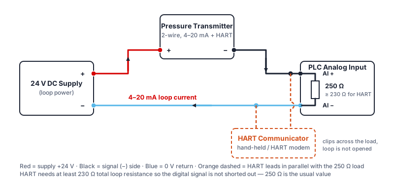
HART superimposes a ±0.5 mA digital signal on the 4-20mA current. The loop must contain at least 230 Ω (250 Ω is the usual PLC burden) or the digital signal is shorted out by the low-impedance supply. Connect the communicator or HART modem in parallel with the burden resistor — never in series — so that the analog reading is undisturbed while you read the process value, range and diagnostic flags.
PLC Signal Scaling: From Raw Counts to Engineering Units
Once the 4-20mA signal reaches the PLC analog input card, it must be scaled to engineering units (bar, PSI, kPa, etc.). With a 250 Ω burden resistor the voltage presented to the AI card is 1–5 V (4 mA × 250 Ω = 1 V; 20 mA × 250 Ω = 5 V).
| Loop Current | Voltage at 250 Ω | % of Range | 14-bit Raw Count (0–16383) | Meaning |
|---|---|---|---|---|
| 0 mA | 0 V | — | 0 | Fault / broken wire |
| 4 mA | 1.00 V | 0% | 3277 | Range minimum (0 bar) |
| 12 mA | 3.00 V | 50% | 9830 | Range midpoint |
| 20 mA | 5.00 V | 100% | 16383 | Range maximum (full scale) |
| > 20.5 mA | > 5.125 V | >100% | >16647 | Over-range or fault |
2-Wire vs 3-Wire: Which Configuration to Choose?
Choose 2-Wire When:
- Simple pressure/level/flow measurement
- Cable runs are long (> 30 m) — fewer wires
- Intrinsically safe (ATEX/IECEx) installations — 2-wire IS barriers are simpler
- Existing 2-conductor cable infrastructure
- Transmitter power consumption < 25 mW at 4 mA
- No local display required
Choose 3-Wire When:
- Transmitter has a built-in LCD display (needs more power)
- HART or Modbus RTU communication required
- High-power signal conditioning electronics
- Transmitter datasheet specifies external power supply
- Multiple output signals (4-20mA + switching output)
- Existing 3-conductor cable infrastructure
A third option, the 4-wire transmitter, keeps the power supply pair and the 4-20mA signal pair fully separate. It is used when the output must be galvanically isolated from the supply — for example when the transmitter and the PLC sit on different ground potentials.
Wiring is only half the job — the transmitter's pressure range, accuracy class (±0.25% FS standard or ±0.1% FS high-accuracy), process connection and wetted materials must also match the application. Our 4-20 mA pressure transmitter selection guide covers range selection, over-pressure margin, accuracy and OEM ordering options step by step.
| Step | Connection | Common mistake to avoid |
|---|---|---|
| 1 | Supply (+) → PWR+, Supply (−) → PWR− | Power wired into the signal terminals — no output, possible damage. |
| 2 | OUT+ → PLC AI (+) | A power wire mixed into the signal pair — offset or noisy reading. |
| 3 | OUT− → PLC AI (−) | Signal return left open — no current, PLC reads 0 mA. |
| 4 | Confirm the PLC input has (or add) a 250 Ω burden | Missing burden resistor — open loop, no reading. |
| 5 | Cable shield → panel ground only | Shield grounded at both ends — ground loop. |
Common Wiring Faults & How to Diagnose Them
These are the four most common 4-20mA installation problems, with root causes and systematic test procedures.
| Symptom | Likely Cause | Diagnostic Step | Fix |
|---|---|---|---|
| 0 mA / no signal at PLC | Broken wire, blown fuse, reversed polarity, transmitter not powered | Measure voltage at transmitter terminals: should be 12–36 V. Measure current with clamp meter in the loop. | Restore wire continuity; check fuse; verify polarity (+/−) |
| Signal stuck at 3.6–4 mA, no response to pressure | Process tap blocked, transmitter electronics fault, isolation valve closed | Apply known pressure at transmitter (use hand pump). Check process connection is open. | Open isolation valve; clean impulse line; replace transmitter if electronics failed |
| Noisy/fluctuating reading in PLC | Ground loop; cable runs near VFDs/motors; shield not grounded correctly | Temporarily shorten cable; measure signal quality near transmitter vs. at panel. Check if noise correlates with motor operation. | Ground shield at panel end only; route cable away from power cables; add galvanic isolator |
| Reading offset — always high or low by fixed amount | Incorrect PLC scaling; wrong burden resistance; transmitter not at true zero | Measure actual current at 0% pressure. Compare with expected 4 mA. Check scaling parameters in PLC AI block. | Re-zero transmitter; correct PLC scaling constants; verify burden resistance |
| Output saturates at 20 mA below full-scale pressure | Burden resistance exceeds transmitter maximum compliance | Calculate total loop resistance (all series devices). Compare with transmitter datasheet maximum burden at 24 V. | Increase supply voltage (to 36 V if transmitter supports it); reduce burden (remove isolators, use lower-resistance AI card) |
| Reversed polarity (+ and − swapped) | Supply (+) landed on the transmitter (−) terminal, or the cable pair colours were assumed rather than checked | Measure voltage at the transmitter terminals with the meter polarity as marked: a negative reading confirms the swap. Most 2-wire transmitters have reverse-polarity protection and simply output 0 mA. | Swap the two conductors at the transmitter; label + and − on both ends; re-check 4 mA at zero pressure |
| Reading constant at 21–22 mA (or 3.6 mA) regardless of pressure | Transmitter is signalling an internal fault or over-range using the NAMUR NE 43 fault band (< 3.6 mA or > 21 mA) | Vent the process connection to atmosphere: a healthy transmitter returns to 4 mA. If it stays in the fault band, read the diagnostic code via HART or check for a ruptured diaphragm / over-pressure event. | Confirm the applied pressure is inside the calibrated range; re-zero; replace the transmitter if the diaphragm or electronics are damaged |
- To measure loop current without breaking the circuit, use a clamp meter around one conductor of the twisted pair. Most industrial clamp meters accurately measure DC currents in the 4-20mA range.
- Alternatively, measure voltage across a known burden resistor: V = I × R. At 250 Ω: 1.000 V = 4 mA, 5.000 V = 20 mA. This is non-invasive and very precise.
- A HART communicator connected across the loop (minimum 230 Ω in the loop) can read the process value digitally and show diagnostic flags, often revealing the fault source without any disassembly.
Download the one-page pressure transmitter datasheet (PDF)
The datasheet lists all ranges from 0–0.1 bar to 0–400 bar, both accuracy classes (±0.25% FS standard, ±0.1% FS high-accuracy), 2-wire 4-20mA and 0–10 V outputs, supply voltage and maximum burden, process connections, wetted materials, temperature limits, IP rating, dimensions and the ordering code. No registration required.
Frequently Asked Questions
4-20mA is a current loop standard where the sensor output is represented as a current between 4 mA (0% of range) and 20 mA (100% of range). Current is used instead of voltage because it is unaffected by cable resistance — only a voltage drop occurs, which does not alter the current measurement. The 4 mA live-zero means a dead transmitter or broken wire produces 0 mA, distinguishable from a valid zero-pressure reading.
A 2-wire transmitter draws its power from the same loop as the signal — supply, transmitter, and load are in series, and only two wires are needed. A 3-wire transmitter has a dedicated power supply pair (Brown = +Vcc, Blue = 0V) and a separate output wire (Black) for the current signal. 2-wire is simpler and dominant in process instruments; 3-wire is used when the transmitter needs more power than a 4-20mA loop can supply.
Maximum burden: R_max = (V_supply − V_transmitter_min) / I_max. With a 24 V supply and 12 V transmitter minimum: R_max = (24 − 12) / 0.020 = 600 Ω. Add up all series resistances: PLC AI card (~250 Ω), cable (~7 Ω per 100 m for 0.5 mm²), barriers, isolators. Total must stay below R_max. Exceeding it causes the output to saturate before reaching 20 mA.
Most pressure transmitters require 12–36 V DC; the industrial standard is 24 V DC regulated. Minimum supply voltage must satisfy: V_supply ≥ V_transmitter_min + (I_max × R_burden). At 20 mA with 250 Ω PLC input (5 V drop) and 12 V transmitter minimum: V_min = 12 + 5 = 17 V. A 24 V supply provides comfortable margin. Use a galvanically isolated, regulated power supply to avoid ground loops.
With a 250 Ω burden, 4 mA = 1 V, 20 mA = 5 V. Formula: Eng_value = (raw − count_at_4mA) / (count_at_20mA − count_at_4mA) × (range_max − range_min) + range_min. For a 14-bit card: count_at_4mA = 3277, count_at_20mA = 16383. Siemens users: FC105 SCALE block. Rockwell users: SCL instruction. Most PLCs provide built-in scaling blocks — check your programming manual for the analog input function block.
0 mA indicates: broken loop wire, reversed polarity, blown fuse, or transmitter with no power. Check: (1) verify supply voltage at transmitter terminals (12–36 V DC); (2) measure loop current with a clamp meter; (3) check polarity — (+) terminal to supply (+). A signal stuck at 3.6–4 mA with no pressure response indicates the process connection is blocked or the transmitter electronics have failed.
Ground loops occur when transmitter and PLC have different earth potentials, causing circulating current that corrupts the 4-20mA signal. Prevention: (1) use a single isolated 24 V DC supply per loop or per instrument group; (2) use PLC AI cards with galvanic isolation; (3) ground cable shields at the panel end only — leave field end unconnected; (4) if ground loops persist, insert a loop-isolating signal conditioner between transmitter output and PLC AI.
Yes, provided the supply has enough current capacity (typically 500 mA to 2 A) and each transmitter has its own return wire to the supply. Do not share a common return between transmitters unless the PLC analog input card explicitly supports it. Treat every loop independently: each transmitter gets its own + and − conductors in the multi-core cable and its own AI channel on the PLC.
Use shielded twisted-pair (STP) cable, 0.5 mm² (20 AWG) minimum conductors. In environments near VFDs or motors, shielded cable is mandatory. Ground the shield at the control panel end only. For cable runs over 200 m, check that loop resistance (both conductors round-trip) stays within your burden budget. Maintain minimum 150 mm physical separation from 230 V AC power cables, run in separate conduit or tray.
Last updated: September 22, 2026 — added HART loop diagram, reversed-polarity and fault-band troubleshooting rows, datasheet download and selection-guide link.