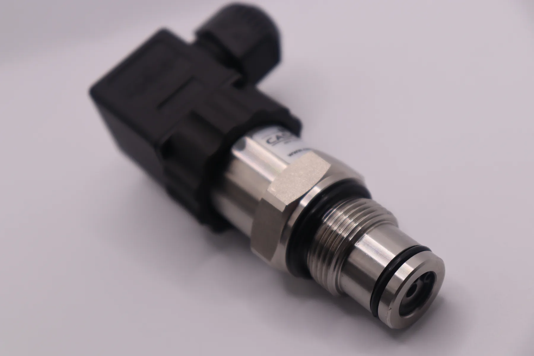
Both devices turn pressure into an electrical signal. The difference is what comes out. A pressure transducer delivers the raw or lightly amplified signal of the sensing element — millivolts per volt of excitation, or a voltage such as 0–5 V or 0.5–4.5 V. A pressure transmitter adds amplification, temperature compensation and a current-loop driver, so it sends a standardized 4–20 mA (or digital) signal that a PLC can read over hundreds of metres of cable. The two names are often used loosely, so always check the output specification rather than the product name.
What is a pressure transducer?
A transducer is any device that converts one form of energy into another. In a pressure transducer, pressure deflects a diaphragm carrying strain-sensitive resistors arranged in a Wheatstone bridge. The bridge is powered by an excitation voltage, and its output changes in proportion to pressure. An unamplified transducer gives only a few tens of millivolts at full scale, specified as mV/V (millivolts of output per volt of excitation), and normally uses four wires: two for excitation, two for signal.
An amplified transducer adds an on-board amplifier and gives a voltage output — commonly 0–5 V, 0–10 V or a ratiometric 0.5–4.5 V — on three wires (supply, signal, common). Voltage outputs are easy to read with a microcontroller ADC, which is why they are common in OEM equipment where the cable is short.
What is a pressure transmitter?
A pressure transmitter is a transducer plus the electronics needed to "transmit" the measurement to a control system: amplification, linearization, temperature compensation and an output stage that drives a standardized signal. The usual signal is the 2-wire 4–20 mA current loop defined in IEC 60381-1, where the same two wires carry both the supply and the measurement. Many transmitters also offer a digital output such as RS485 Modbus RTU, IO-Link or HART. Performance of process transmitters is evaluated under IEC 60770-1. See the 4–20 mA pressure transmitter page for SEGMENsensor ranges and connections.
How does the signal chain differ?
The output of each stage follows a simple formula:
mV transducer: Vout = S × Vexc × P / PFS
4–20 mA transmitter: I = 4 mA + 16 mA × P / PFS
Worked example: take a 0–10 bar bridge with an illustrative sensitivity S = 2 mV/V and 10 V excitation. Full scale is only 20 mV, so 1 mbar of pressure is 2 µV — easily buried by noise picked up on a long cable. The same 0–10 bar range as a 4–20 mA transmitter outputs 4 + 16 × 6/10 = 13.6 mA at 6 bar, a signal large enough to survive industrial wiring. Convert any reading with the 4–20 mA to pressure calculator.
Pressure transducer vs pressure transmitter: comparison table
| Criterion | Pressure transducer | Pressure transmitter |
|---|---|---|
| Output | mV/V (unamplified) or voltage: 0–5 V, 0–10 V, 0.5–4.5 V ratiometric | 4–20 mA current loop, or digital (RS485 Modbus RTU, IO-Link, HART) |
| Wiring | 4-wire (mV bridge) or 3-wire (voltage) | 2-wire loop-powered (4–20 mA) |
| Cable length | Short: voltage drop and noise on the wire change the reading | Long: loop current is the same at every point, limited only by the loop-resistance budget |
| Noise immunity | Low (mV) to moderate (V) | High — a low-impedance current signal |
| Fault detection | 0 V can mean zero pressure or a broken wire (0.5–4.5 V outputs reserve the ends for faults) | Live zero: 4 mA = zero pressure, near 0 mA = broken loop |
| Receiver | Bridge amplifier, strain-gauge module or microcontroller ADC | Standard PLC / DCS analog input, panel meter or recorder |
| Typical uses | OEM boards, compressors, test benches, battery-powered loggers | Process plants, hydraulic systems, water networks, remote tanks |
How far can a 4–20 mA signal travel?
As far as the loop-resistance budget allows. The transmitter needs a minimum voltage at its terminals; everything else in the loop — cable and PLC input resistor — must fit within the remaining supply voltage at 20 mA:
Rmax = (Vsupply − Vmin) / 0.020 A
With a 24 V supply and a 12 V minimum, Rmax = (24 − 12) / 0.020 = 600 Ω, which is the SEGMENsensor transmitter specification. Subtract a typical 250 Ω PLC input and 350 Ω remains for the cable. Copper has a resistivity of about 0.0175 Ω·mm²/m, so a 0.5 mm² pair (two conductors) is roughly 70 Ω per km of route — in theory about 5 km. In practice, keep a margin and follow the 4–20 mA wiring guide.
Which one should you choose?
Choose a transducer (mV or voltage output) when the electronics sit within a few metres of the sensor, you control the input circuit, and you want low power or a compact OEM part.
Choose a transmitter (4–20 mA or RS485) when the signal goes to a PLC or DCS, the cable is long or runs next to motors and drives, or you need broken-wire detection. For an on/off duty with no controller, compare a pressure switch vs pressure transmitter instead.
- Range and reference — 0–0.1 to 0–400 bar; gauge, absolute or sealed (see gauge vs absolute vs differential).
- Output — 4–20 mA, 0–10 V or RS485 Modbus RTU.
- Accuracy — ±0.25% FS standard or ±0.1% FS high-accuracy.
- Connection and protection — G1/4, G1/2, 1/4 NPT, 1/2 NPT; IP67 or IP68 per IEC 60529.
The full checklist is in the 4–20 mA pressure transmitter selection guide; convert bar, psi and kPa with the pressure unit converter.
Frequently Asked Questions
"Pressure sensor" is the general term. Strictly, the sensor is the sensing element; the transducer is the element packaged to give an electrical output; the transmitter adds conditioning and a standardized output. In everyday use the three words overlap, so check the output signal on the datasheet.
Not to a standard analog input. A millivolt bridge needs a strain-gauge or bridge-input module, or a separate signal conditioner, that supplies excitation and amplifies the signal. A 4–20 mA transmitter connects to a standard PLC current input.
In a series loop the current is the same at every point, so cable resistance does not change the reading as long as the total stays within the loop budget (600 Ω at 24 V for SEGMENsensor transmitters). A voltage signal loses part of its value across the cable and picks up more noise.
The output is a fixed fraction of a 5 V supply: 10% (0.5 V) at zero pressure and 90% (4.5 V) at full scale. Readings below 0.5 V or above 4.5 V indicate a fault such as a short or open circuit, and reading the ADC against the same 5 V reference cancels supply drift.
SEGMENsensor makes pressure transmitters from 0–0.1 to 0–400 bar at ±0.25% FS or ±0.1% FS, with 2-wire 4–20 mA, 0–10 V or RS485 output, 12–36 V DC supply, -40 to +125 °C media temperature and IP67 (IP68 on request).
MOQ is 1 piece. Samples ship in 5–7 working days and production orders in 3–5 weeks. Quotations are FOB China with 100% T/T in advance, and we reply to inquiries within 24 hours.