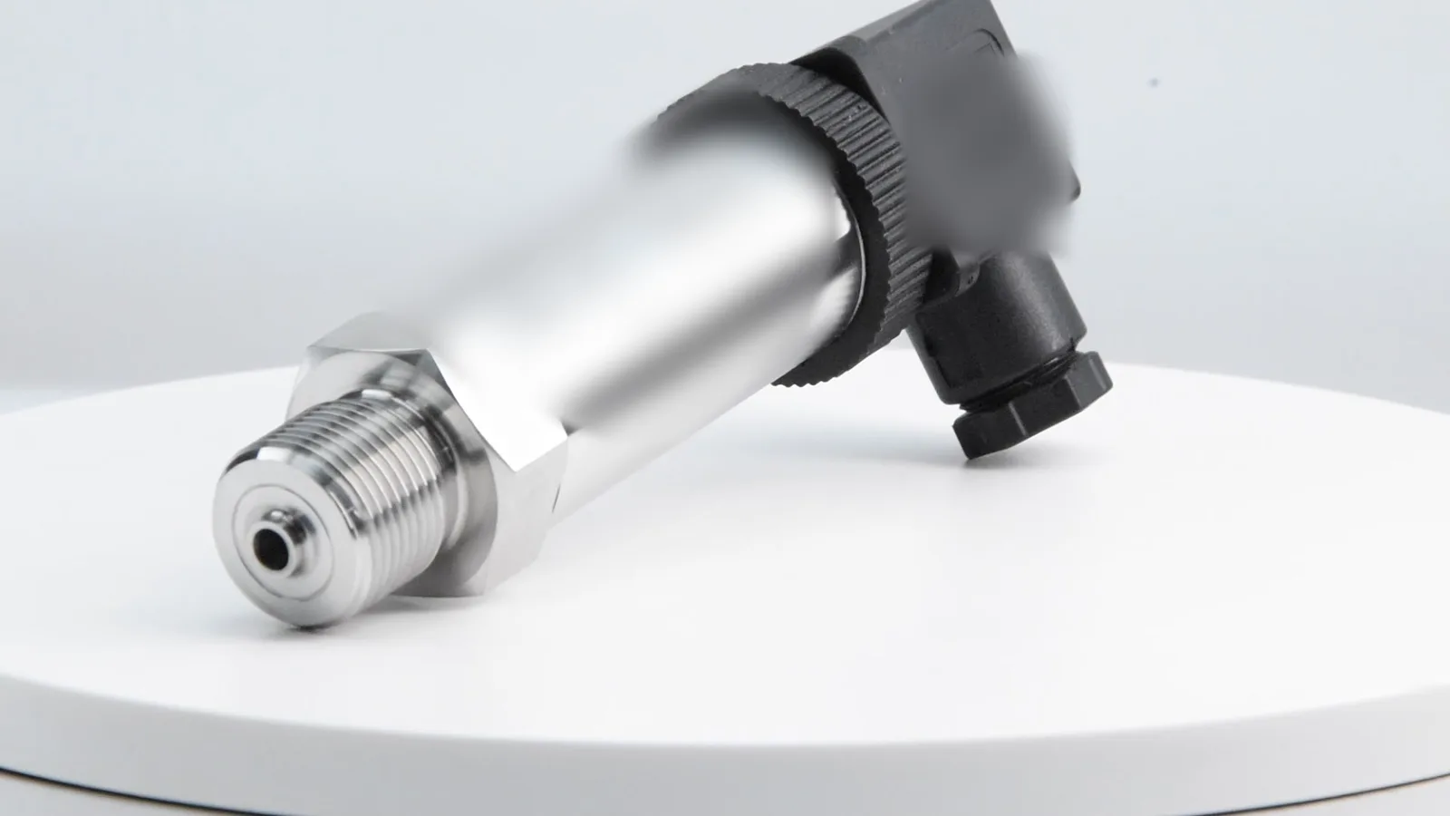
A pressure snubber (also called a pressure dampener or pulsation damper) is a restrictor — a porous metal disc, a small piston or an adjustable needle — screwed in front of a pressure instrument. Fit one when the line sees pump pulsation, hydraulic valve switching or water hammer: these make gauge needles flutter, switches chatter and transmitter readings jump, and repeated spikes above the overpressure rating can permanently shift a sensor’s zero. Do not fit one where the medium can clog it or where the measurement must follow fast pressure changes.
How does a pressure snubber work?
A pressure change can only reach the sensing diaphragm if a small volume of fluid flows through the port into the instrument’s cavity. The snubber makes that path narrow. Steady pressure still gets through completely, because once the cavity is filled no more flow is needed. A fast spike, however, is over before enough fluid has passed, so the diaphragm sees a lower, slower peak.
In a simple first-order model the restriction is a flow resistance R and the fluid volume behind it is a compliance C, exactly like a resistor–capacitor filter in electronics. Real snubbers are not perfectly linear — the effect depends on viscosity, temperature and the size of the spike — so treat the numbers below as a way to understand the trade-off, not as a data-sheet value.
How much does a snubber reduce pulsation? Formulas and example
| Quantity | Formula | Example |
|---|---|---|
| Pump pulsation frequency | f = (n / 60) × z (× 2 for double-acting pistons) | 1,450 rpm, 3 pistons → 24.2 × 3 ≈ 72.5 Hz |
| Water-hammer surge (Joukowsky) | Δp = ρ × a × Δv | 1000 kg/m³ × 1200 m/s × 1 m/s = 1.2 MPa = 12 bar |
| Cut-off frequency | fc = 1 / (2πτ) | τ = 0.1 s → fc ≈ 1.6 Hz |
| Remaining ripple (first order) | Aout / Ain = 1 / √(1 + (f / fc)²) | 72.5 Hz / 1.6 Hz → ≈ 0.022, about 2% |
| Response to a real step | 63% after 1τ, 95% after 3τ | τ = 0.1 s → 95% after 0.3 s |
Here n is pump speed in rpm, z the number of pistons, ρ the fluid density, a the pressure-wave speed in the pipe (about 1000–1400 m/s for water in steel pipe) and Δv the sudden change in flow velocity. Convert between bar, psi and kPa with the pressure unit converter.
Worked example: transmitter on a triplex plunger pump
- The pump runs at 1,450 rpm with 3 plungers, so the pressure ripple is at about 72.5 Hz around a mean of 60 bar.
- Without damping, a 4–20 mA transmitter follows the ripple and the PLC sees a noisy value; a pressure switch set near 60 bar would chatter.
- A snubber with an effective τ of 0.1 s cuts the ripple to roughly 2% of its original amplitude, while the 60 bar mean is unchanged.
- Check the trade-off: a genuine pressure change now takes about 0.3 s to show 95% of its value. That is fine for monitoring, but may be too slow for a fast safety trip.
- Check the peak: with a 0–100 bar transmitter rated 2×, the overpressure limit is 200 bar. If the unsmoothed peaks can approach that value, the snubber is protection, not just cosmetics. The overpressure vs burst pressure guide explains the limits.
When do you need a pressure snubber?
Fit one when the pressure source creates fast changes that the instrument does not need to follow. Avoid one when the medium can block it or when the fast changes are what you want to measure.
| Situation | Snubber? | Why |
|---|---|---|
| Piston, plunger or diaphragm pump discharge | Yes | Periodic pulsation makes readings jump and fatigues the diaphragm |
| Hydraulic presses, cylinders, fast directional valves | Yes | Switching and end-of-stroke impacts create sharp peaks |
| Fast-closing valves or check valves in water lines | Yes | Water hammer can briefly reach several times the operating pressure |
| Pressure switch chattering near its set point | Yes | Smoothing stops rapid on/off cycling of the contact |
| Slurry, viscous, crystallising or fibrous media | No | The restriction clogs; use a flush diaphragm or diaphragm seal instead |
| Dynamic pressure, leak or burst detection | No | The measurement must follow fast changes |
| Slow processes: tank levels, HVAC, water supply without surges | Usually not | Nothing fast to remove |
A snubber is not a substitute for proper overpressure protection of the system. ISO 4413 — Hydraulic fluid power: general rules and safety requirements ↗ requires hydraulic systems to be protected against pressures above the rated limits of their components, typically with relief valves; the snubber protects the instrument against short peaks only.
Pulsating or surging line?
Send us the normal pressure, the peak or pulsation source (pump type, valve, compressor) and the medium. We will suggest a range and overload rating, and confirm with the quotation whether a damping option is available for that model. MOQ 1 pc · samples in 5–7 working days · production 3–5 weeks · reply within 24 hours.
What types of pressure snubbers are there?
| Type | How it restricts flow | Adjustable | Suited to | Watch out for |
|---|---|---|---|---|
| Porous (sintered) metal disc | Fluid passes through the pores of a sintered stainless disc | No — choose the grade for the fluid viscosity | Clean gases, air, water, light oils | Clogs with dirty media |
| Piston type | A loose piston in a bore; fluid flows through the small clearance, and the piston movement helps keep it clean | No — choose the piston for the fluid | Hydraulic oil, water, pump discharge lines | Must be mounted as specified by its maker |
| Needle valve / adjustable snubber | A needle sets the orifice size | Yes | Tuning damping on site | Can be closed by mistake — the reading then freezes |
| Fixed orifice / restrictor screw | A small drilled hole in the port or an insert | No | Compact damping built into the connection | Very small holes block easily |
Two parts are often confused with snubbers. A siphon (pigtail) protects an instrument from hot steam by holding a column of condensate; it does not damp pulsation. A diaphragm seal separates the sensor from aggressive or clogging media; it can be combined with damping but is not a snubber.
Snubber or electronic damping: which one protects the sensor?
Only the mechanical snubber. Electronic damping (a filter time in the transmitter or the PLC) smooths the output signal, but the diaphragm still sees every spike at full height. If peaks can exceed the overpressure rating, the diaphragm can deform permanently and the sensor shows a zero offset or span error. Use electronic filtering for a calm reading and a snubber when the sensing element itself needs protection. Test methods for transmitter performance, including the effect of overload, are described in IEC 62828-1 — Reference conditions and procedures for testing industrial and process measurement transmitters ↗.
How do you install a pressure snubber?
- Position: screw it directly into the instrument port, between the isolation valve and the gauge, switch or transmitter.
- Thread: match the instrument thread; SEGMENsensor transmitters use G1/4 (standard), G1/2, 1/4 NPT or 1/2 NPT.
- Orientation: follow the maker’s marking; for liquids, mount the instrument below the tapping so gas can escape, and for gases above it so condensate drains back.
- Commission: open the isolation valve slowly and compare the reading with a reference; with an adjustable snubber, close it only until the reading is steady.
- Maintain: if the reading becomes sluggish or stays fixed while the process changes, clean or replace the snubber before suspecting the sensor.
Which SEGMENsensor pressure sensors work with a snubber?
| SEGMENsensor product | Rated range | Overload rating | Typical snubber use |
|---|---|---|---|
| 4–20 mA pressure transmitter | 0–0.1 bar to 0–400 bar | 2–5× rated range | Pump discharge, hydraulics, compressed air |
| SYK102 mechanical pressure switch | 0.5–8.5 bar adjustable | 1.5× rated range | Booster pumps and compressors with pulsation or chattering |
| Vacuum pressure switch | −1 to 0 bar | 2× rated range | Rarely needed |
Transmitter accuracy is ±0.25% FS (±0.1% FS high-accuracy), with 4–20 mA, 0–10 V or RS485 output; all models are on the pressure sensor page. For viscous media, a flush-diaphragm version in G1/2" or 1" avoids a narrow port altogether. Check the output for any pressure with the 4–20 mA calculator, and see the pressure transmitter selection guide for range and output choice. Quotations are FOB China, payment 100% T/T in advance.
Frequently Asked Questions
It restricts the flow of fluid into a pressure gauge, switch or transmitter. Steady pressure passes unchanged, but fast spikes and pulsation are smoothed, so the reading is calm and the sensing element is protected from short pressure peaks.
No. Once the instrument cavity is filled, no more flow is needed, so the steady pressure is the same with or without a snubber. Only the amplitude and speed of fast changes are reduced.
Avoid it with slurries, viscous, crystallising or fibrous media, which clog the restriction, and where the measurement must follow fast changes, such as dynamic pressure, leak or burst detection. Use a flush diaphragm or a diaphragm seal for difficult media.
No. A siphon protects an instrument from hot steam by holding a column of condensate. A snubber damps pressure pulsation and spikes. Steam service can need a siphon, and a pulsating line a snubber.
Only for a steadier signal. Electronic damping filters the output, but the diaphragm still receives every spike at full height. If peaks can exceed the overpressure rating, a mechanical snubber or a higher overload rating is needed.
Yes. SEGMENsensor 4–20 mA pressure transmitters cover 0–0.1 to 0–400 bar with a 2–5× overload rating. Tell us the pulsation source and peak pressure, and we confirm the range, overload rating and any damping option with the quotation. MOQ is 1 piece, samples ship in 5–7 working days, production takes 3–5 weeks, quotations are FOB China, and we reply within 24 hours.