HART is a hybrid analog-plus-digital protocol for field instruments. The transmitter still sends its main measurement as a 4–20 mA current, while a host, handheld communicator or asset-management system exchanges digital messages over the same two wires at 1200 bit/s. Engineers use HART to set range and damping, read device status and diagnostics, and pull up to four process variables from one instrument — without new cabling.
How does HART communication work on a 4–20 mA loop?
A conventional 2-wire transmitter regulates the loop current between 4 mA (lower range value) and 20 mA (upper range value), as defined for direct-current process signals in IEC 60381-1. HART leaves that current untouched and adds a low-level AC signal on top of it. The modem in the transmitter and the modem in the host shift between two frequencies — 1200 Hz for a 1 and 2200 Hz for a 0 — using the Bell 202 frequency-shift-keying scheme.
Because the sine wave is only about ±0.5 mA and its average over each bit is zero, an analog input card that averages the current still reads exactly the same value. The digital data rides along for "free": no extra wires, no change to intrinsic-safety barriers designed for the loop, and no change to the 4–20 mA control strategy.
HART is a master–slave protocol. The field device answers when asked. Two masters are allowed on one loop: the primary master (usually the control system or a HART multiplexer) and a secondary master (typically a handheld communicator or a laptop with a HART modem clipped across the loop resistor).
What does a HART loop look like?
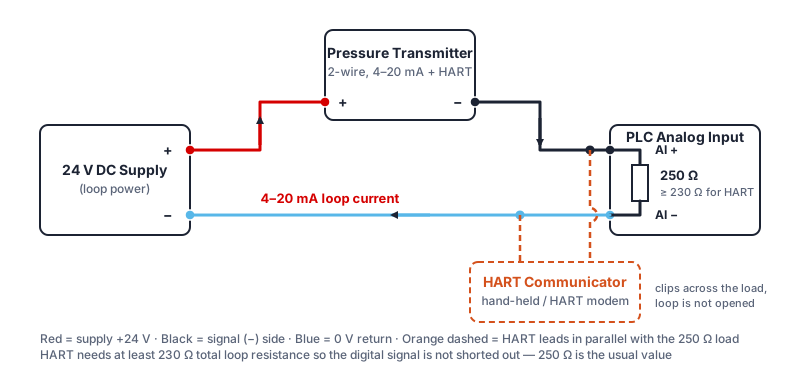
The diagram shows the minimum hardware: a 24 V DC supply, the transmitter, the PLC analog input and a load resistor of at least 230 Ω. The HART communicator or modem connects in parallel with that resistor — or anywhere across the transmitter terminals — so commissioning and diagnostics never interrupt the measurement. For the full terminal-by-terminal wiring, see our guide to 4–20 mA pressure transmitter wiring.
Before adding HART, check the loop budget. The supply must still push 20 mA through every resistance in the loop: the HART resistor, the analog input, barriers and cable. On SEGMENsensor 4–20 mA transmitters the supply range is 12–36 V DC with a maximum loop resistance of 600 Ω at 24 V, so a 250 Ω HART resistor leaves margin for cable and barrier resistance. Our 4–20 mA calculator converts loop current to pressure and helps check the numbers.
HART at a glance: key technical values
| Parameter | Typical HART value | What it means in practice |
|---|---|---|
| Physical layer | Bell 202 FSK on the 4–20 mA pair | No extra wires; works on existing twisted-pair cable |
| Frequencies | 1200 Hz = 1, 2200 Hz = 0 | Filtered out by normal analog input cards |
| Data rate | 1200 bit/s | About 2–3 digital updates per second point-to-point |
| Signal amplitude | ±0.5 mA, zero average | Analog 4–20 mA reading is unchanged |
| Minimum loop resistance | 230 Ω (250 Ω typical) | Without it the HART signal is shorted by the supply |
| Masters per loop | 2 (primary + secondary) | Control system and handheld can both talk to the device |
| Multidrop devices | 15 (HART 5) / 63 (HART 6/7) | Each device fixed at 4 mA; digital data only |
| Dynamic variables | PV, SV, TV, QV | Up to four measured values from one instrument |
What can engineers do with HART?
HART commands fall into three groups: universal commands that every HART device must support (read the primary variable, tag, range and unit), common-practice commands that many devices share (set damping, re-range, loop test), and device-specific commands defined by the manufacturer in the device description (DD) file. In daily work that means:
- Remote re-ranging — change the lower and upper range values without applying a reference pressure at the instrument.
- Loop checks — force the output to 4, 12 or 20 mA and confirm the PLC reads the same value during commissioning.
- Diagnostics — read device status bits such as sensor fault, electronics fault or output saturated, before a reading drifts out of tolerance.
- Extra variables — a pressure transmitter can report sensor temperature as a secondary variable; a level transmitter can report level and interface or temperature.
- Asset records — read tag, serial number, firmware revision and calibration date for maintenance planning.
HART vs plain 4–20 mA vs RS485 Modbus RTU
HART is not the only way to get digital data from a sensor. The table below helps decide which output to specify.
| Criterion | 4–20 mA only | 4–20 mA + HART | RS485 Modbus RTU |
|---|---|---|---|
| Main value | Analog current | Analog current + digital | Digital register |
| Extra variables and diagnostics | No (fault current only) | Yes, over the same 2 wires | Yes, via registers |
| Remote configuration | No | Yes | Yes (device-dependent) |
| Devices per cable | 1 | 1 (or multidrop at 4 mA) | Many on one bus |
| Best fit | Simple PLC loops, OEM machines | Process plants with existing 4–20 mA DCS and asset management | Skids, data loggers, multi-sensor buses |
As a rule: keep plain 4–20 mA for simple machines, choose HART when a process plant already runs 4–20 mA and wants diagnostics without rewiring, and choose RS485 when many sensors share one bus. For help choosing a range and output, read our 4–20 mA pressure transmitter selection guide.
Need a HART transmitter specified for your loop?
Send range, media, process connection and HART requirement to our engineers. MOQ 1 pc · samples in 5–7 working days · reply within 24 hours.
Which SEGMENsensor transmitters can be supplied with HART?
HART is a project option rather than a stock catalogue item at SEGMENsensor: we confirm the model, configuration and lead time at quotation. The table lists the published parameters of the product lines where HART can be requested.
| Product line | Published range and accuracy | Standard outputs | HART |
|---|---|---|---|
| 4–20 mA pressure transmitter | 0–0.1 to 0–400 bar; ±0.25% FS, ±0.1% FS high-accuracy | 2-wire 4–20 mA, 0–10 V, RS485 | On request, selected models |
| SE-LX magnetostrictive level transmitter | 200–8000 mm | 2-wire 4–20 mA, 0–10 V, RS485 | On request (2-wire 4–20 mA) |
| Supply / loop | 12–36 V DC; maximum loop resistance 600 Ω at 24 V DC (4–20 mA pressure transmitters) | Fits a 250 Ω HART resistor | |
| Commercial terms | MOQ 1 piece · samples 1–5 pcs in 5–7 working days · production 3–5 weeks · FOB China · 12-month warranty | ||
Download the one-page datasheet (PDF)
The pressure transmitter datasheet lists the available ranges, both accuracy classes, output options, supply voltage, process connections, wetted materials, temperature limits, IP rating, dimensions and the ordering code. No registration required.
Why will a HART device not communicate?
Most HART problems on site come down to a few causes. Check them in this order:
- Loop resistance below 230 Ω — the supply shorts the HART signal. Add a 250 Ω resistor in series, or connect the communicator across an existing resistor of the right value.
- Communicator in the wrong place — it must be across the load resistor or the transmitter terminals, not across the power supply.
- Wrong polling address — a device set to a non-zero address in point-to-point mode may hold its output at 4 mA; set the address back to 0 for analog operation.
- Noise or long cable runs — use shielded twisted pair, ground the shield at one end and keep it away from VFD and power cables.
- Missing device description — the host can read universal commands but needs the correct DD file for device-specific settings.
Transmitter performance — accuracy, temperature effect and long-term stability — is evaluated under the methods in IEC 60770-1; HART only changes how you read and configure the device, not how accurately it measures.
Frequently Asked Questions
No. The HART signal is a ±0.5 mA sine wave whose average over each bit is zero, so a PLC analog input that filters or averages the loop current still reads the same 4–20 mA value. Only the digital receiver in a HART modem or host sees the frequency-shift-keyed data.
The loop needs at least 230 Ω of resistance between the power supply and the transmitter so the HART voltage can develop; a 250 Ω resistor is the usual choice. Check that the supply can still drive 20 mA through the total loop resistance — on SEGMENsensor transmitters the limit is 600 Ω at 24 V DC.
HART runs at 1200 bit/s, which in point-to-point mode gives roughly two to three digital updates per second. That is fine for configuration, diagnostics and secondary variables, but the 4–20 mA signal remains the fast, continuous control value.
In multidrop mode HART 5 devices use polling addresses 1 to 15, and HART 6 and HART 7 extend the address range to 63. Each device is parked at a fixed 4 mA, so the loop carries digital data only and the analog value is no longer available.
HART is available on request for selected SEGMENsensor pressure transmitters and for the SE-LX magnetostrictive level transmitters (200–8000 mm) with 2-wire 4–20 mA output. Tell us the range, connection and HART requirement and we confirm the model, lead time and quotation within 24 hours. MOQ is 1 piece.
Last updated · SEGMENsensor Engineering Team