Submersible Level Transmitter — 4-20mA, IP68, OEM China Factory
SEGMENsensor submersible (hydrostatic) level transmitters measure liquid depth by sensing hydrostatic pressure at the bottom of tanks, wells, reservoirs, and boreholes. Stainless steel 316L probe, ceramic or piezoresistive sensing element, 4-20mA or 0-10V output. IP68 submersion rated. CE and RoHS certified. OEM from Shenzhen since 2019, OEM volume supply.
CE CertifiedIP68 Rated316L SS ProbeOEM volume supply
Key facts
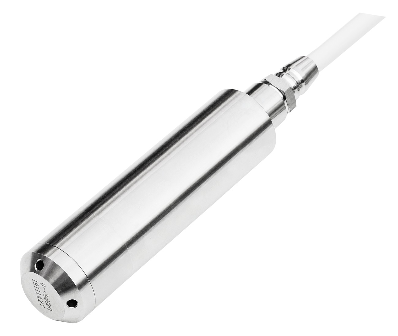
A SEGMENsensor submersible level transmitter is a sealed hydrostatic probe that sits at the bottom of a tank, well or reservoir, measures the pressure of the liquid column above it and converts it to a 4-20 mA or 0-10 V signal proportional to depth. The probe is 316L stainless steel, rated IP68 for permanent submersion.
Measuring range is 0–0.5 mWC to 0–200 mWC, specified at order.
Supply is 12–36 V DC and process temperature is -20 to +80 °C.
The standard thread is G1/2"; qualification samples are 1–5 pcs.
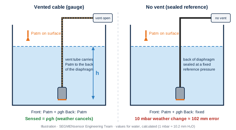
The vent tube in the cable cancels atmospheric pressure; without it, a 10 mbar weather change would read as about 102 mm of water (calculated value, see how compensation works).
Last updated · SEGMENsensor Engineering Team
Watch: installation, 4–20 mA wiring and the working principle
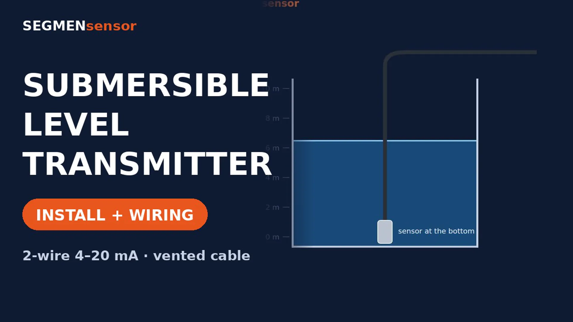
Submersible Level Transmitter: Installation and 4–20 mA WiringWhere to place the probe, stilling pipe and vented cable, 2-wire 4–20 mA wiring to a PLC, scaling the signal on a 0–10 m range, and what to specify before ordering.
Submersible level transmitters: how to install and wire them for a stable reading. The probe sits at the bottom and measures the pressure of the liquid above it. For water, 1 m gives about 0.1 bar. A small vent tube in the cable connects the sensor to the air, so changes in atmospheric pressure cancel out. To install, lower the probe to the bottom of the tank or well, and keep it clear of sludge. In moving or turbulent liquid, guide the probe in a stilling pipe so it hangs still. Keep the vent tube open to the air and dry. End the cable in a vented junction box. Wiring is a 2-wire loop: one cable pair carries both the 12–36 V DC supply and the 4–20 mA signal. Connect the supply positive to the transmitter, and the transmitter's return to the analog input of the PLC. On a 0–10 m range, 4 mA is empty, 12 mA is 5 m and 20 mA is full. To convert: subtract 4 mA, divide by 16 mA, multiply by the range. Specify the range (0.5–200 mWC) and the cable length: 5 m standard, or made to your installation depth. Standard accuracy is ±0.1% FS, with a 316L stainless steel probe rated IP68. For chemical media, a PTFE cable is available. On the production line, sealed stainless assemblies are pressurised with air and held under water, where any leak would show as bubbles. Housings are checked before assembly. SEGMENsensor submersible level transmitters. OEM volume supply. Quotes at segmensensor.com.
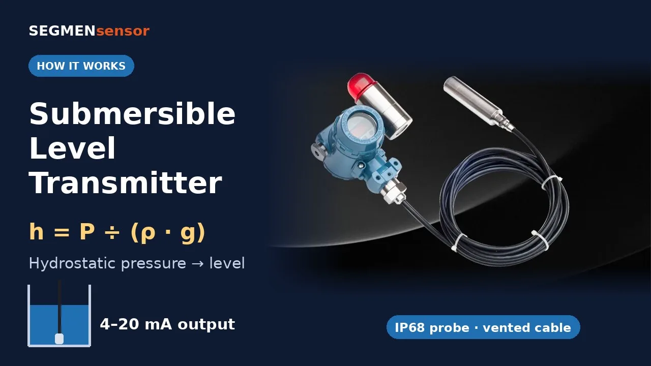
How a Submersible Level Transmitter WorksOne-minute animation of hydrostatic level measurement: pressure at the bottom of the tank, h = P ÷ (ρ·g), the vented cable that cancels atmospheric pressure, and scaling the level to 4–20 mA.
How does a submersible level transmitter measure level? The transmitter sits at the bottom of the tank. The higher the liquid, the higher the pressure on the sensor. Pressure = density × gravity × height, so height is pressure divided by density and gravity. For water, 1 m gives about 0.1 bar. A small vent tube in the cable connects the sensor to the atmosphere, so changes in air pressure cancel out. The output is 4–20 mA. On a 0–10 m range, 4 mA is empty, 12 mA is 5 m, and 20 mA is full. SEGMENsensor submersible level transmitters: 0.5–200 mWC. Try our level calculator at segmensensor.com.
What is a Submersible Level Transmitter?
A submersible level transmitter (also called a hydrostatic level sensor or pressure level probe) is a sealed, waterproof sensor installed at the bottom of a liquid vessel. It measures the hydrostatic pressure of the liquid column above it and converts this to a 4-20mA or 0-10V signal proportional to liquid depth. Sensing range is expressed in meters of water column (mWC) — a 10m range sensor measures 0 to 10 meters of water depth, outputting 4mA at empty and 20mA at full. Step-by-step principle, density correction and drift causes: how a hydrostatic level sensor works.
How do you convert pressure to liquid level? A worked example
Liquid level equals pressure divided by density times gravity: h = P ÷ (ρ·g). For water (ρ ≈ 1000 kg/m³), each metre of depth adds about 9.81 kPa (0.0981 bar). Example, calculated values: a 0–5 m range in water reads 5 × 9.81 = 49.05 kPa (about 0.49 bar) at full scale. A live reading of 12 mA is (12 − 4) ÷ 16 = 50% of the span, so the level is 2.5 m. For other liquids, use the density of your liquid; try your own numbers in the hydrostatic tank level calculator.
Specifications
Submersible Hydrostatic Level Transmitter — Full Specification Table
Standard SEGMENsensor submersible level transmitter specifications. Custom range, cable length, output signal, and connector available from OEM volume supply.
5 m standard (custom length to installation depth)
Supply Voltage
12–36V DC
Process Temperature
-20°C to +80°C
Thread / Process Connection
G1/2" (standard), 3/4" NPT, 1" BSP custom
Samples
Samples 1–5 pcs for qualification; volume per project
Lead Time
Confirmed with the quotation (standard production); samples 1–5 pcs in 5–7 days; custom OEM confirmed at order
Certifications
CE, RoHS
Download the submersible level transmitter datasheet (PDF)
One-page datasheet with all ranges, accuracy classes, output options, supply voltage, process connections, materials, temperature limits, IP rating, dimensions and the ordering code. No registration required.
Submersible Level Transmitter OEM — 8 Industry Applications
From groundwater monitoring to CDU coolant reservoirs — SEGMENsensor submersible level transmitters are specified for continuous immersion in demanding liquids.
🌊
Groundwater Wells
Borehole water table monitoring for agriculture and municipal water. Long cable made to the well depth, 0–20 mWC or 0–40 mWC range typical for deep wells.
🏭
Water Treatment Tanks
Reservoir and clarifier level measurement. Ceramic diaphragm suits clean and mildly turbid water. 4-20mA connects directly to SCADA systems.
♻️
Wastewater Sumps
Lift station wet well level control. IP68 continuous submersion with vented cable. 316L SS housing resists hydrogen sulfide exposure common in wastewater environments.
⚗️
Industrial Process Tanks
Chemical storage tank level monitoring. Specify process medium at order — ceramic for mild chemicals, 316L SS diaphragm for light acids or hydrocarbons.
❄️
Cooling Water Systems
Cooling tower basin and CDU coolant tank level measurement. Compatible with propylene glycol / water mixtures up to 50% PG. 0–1 or 0–2 mWC range for typical CDU depths.
⛽
Fuel Oil Tanks
Underground fuel storage tank level. Specify 316L SS diaphragm and oil-compatible Viton seal. PTFE cable recommended for diesel and light fuel oil environments.
⚓
Marine Bilge Monitoring
Bilge water level detection on vessels. IP68 continuous submersion rated to full working depth. Compact probe diameter fits standard bilge bilge well tube installations.
🌾
Agricultural Irrigation
Open channel and pond water depth measurement. Vented cable equalizes atmospheric pressure changes for accurate level in open water bodies regardless of barometric variation.
Selection Guide
How to Select a Submersible Level Transmitter — 3 Configuration Paths
Match your process medium, accuracy requirement, and installation environment to the right SEGMENsensor submersible transmitter configuration.
💧
Standard Water / Wastewater Most common configuration
Specify media when requesting quote for seal/cable compatibility check
Output: 4-20mA or 0-10V
→ 316L SS diaphragm + PTFE cable version
🎯
High Accuracy / Metering ±0.05% FS precision
Accuracy requirement: ±0.05% FS (vs standard ±0.1% FS)
Built-in temperature compensation circuit
Suitable for custody transfer, batching, and dosing applications
Calibration certificate included with each unit
Output: 4-20mA HART optional
→ High accuracy ±0.05% FS version
Not sure which configuration fits your media and depth?
Tell us your liquid type, tank depth, operating temperature, and output requirements — our engineers will specify the exact model and range within 24 hours.
Submersible Level Transmitter by Application — Range, Wetted Material, Cable and Vent Selection Table
Use this table to pre-select a SEGMENsensor submersible level transmitter for wells, storage tanks, wastewater sumps, chemical tanks and coolant reservoirs. Final configuration is confirmed by our engineers from your liquid, depth and output requirement.
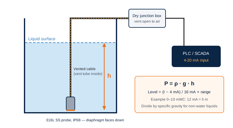
Fig. 2 — Typical installation: the probe hangs on its vented cable near the tank bottom, the vent tube ends in a dry junction box, and the 4-20 mA signal scales linearly with the liquid column height h.
Application
Typical range
Diaphragm / housing
Cable
Vent and installation note
Output
Groundwater well / borehole
0–20 or 0–40 mWC
Ceramic (Al₂O₃) + 316L SS
PVC vented, custom length to well depth
Order cable length = well depth + run to the wellhead; fit the desiccant vent plug outdoors
4-20 mA 2-wire
Water treatment tank / reservoir
0–5 or 0–10 mWC
Ceramic (Al₂O₃) + 316L SS
PVC vented, 5 m standard
Terminate the vent end in a dry junction box above the maximum level
4-20 mA to SCADA
Wastewater sump / lift station
0–5 or 0–10 mWC
Ceramic or 316L SS diaphragm, 316L SS housing
PVC vented
Hang the probe away from the pump inlet; keep the vent open to atmosphere
4-20 mA 2-wire
Chemical storage tank
Sized to tank height (0–0.5 to 0–200 mWC)
316L SS diaphragm; PVDF housing + PTFE-lined probe for aggressive media
PTFE vented
State the medium and concentration at RFQ for a seal and cable compatibility check
4-20 mA or 0-10 V
CDU coolant reservoir / cooling tower basin
0–1 or 0–2 mWC
Ceramic (Al₂O₃) + 316L SS, PG/water up to 50% PG
PVC vented
Confirm material compatibility for deionized-water loops
4-20 mA to CDU controller
Fuel oil / diesel tank
Sized to tank height
316L SS diaphragm + Viton seal
PTFE vented
Apply the specific gravity of the fuel in the PLC scaling
4-20 mA
Batching, dosing, metering
0–0.5 to 0–200 mWC
High-accuracy version, ±0.05% FS
PVC or PTFE vented
Built-in temperature compensation; calibration certificate per unit
4-20 mA
Scaling the 4-20 mA signal to level
Level (m) = (I − 4 mA) ÷ 16 mA × range. With a 0–10 mWC transmitter, 4 mA reads 0 m, 12 mA reads 5 m and 20 mA reads 10 m. Because the transmitter is calibrated in metres of water column, divide the reading by the specific gravity of any liquid that is not water (brine, acid, fuel oil) to get the true depth.
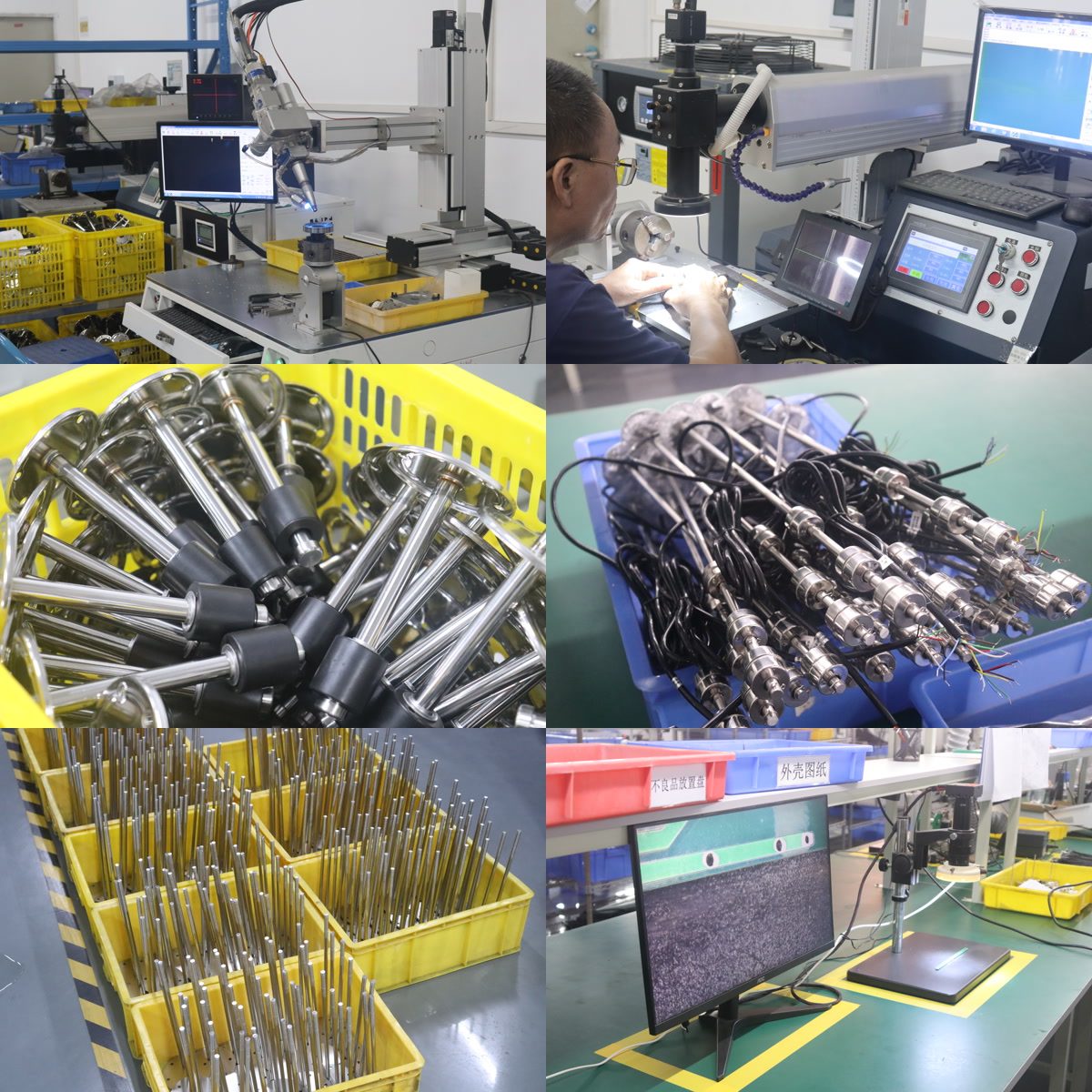
Laser welding, inspection and level sensor assembly at the SEGMENsensor factory, Shenzhen.
Send your application row — we configure the transmitter for you
Tell us the liquid, maximum depth, cable length, output and connector. Qualification samples of 1–5 pcs ship in 5–7 days, production lead time confirmed with the quotation, and every inquiry gets a reply within 24 hours. The one-page datasheet (PDF) lists all ordering options.
How does a submersible level transmitter compensate for atmospheric pressure?
A submersible level transmitter compensates for atmospheric pressure through the vent tube inside its cable: the tube carries air pressure to the back of the sensing diaphragm, so air pressure acts equally on both sides and cancels, and the 4-20 mA output follows only the liquid column (ρ·g·h). That is why SEGMENsensor ships a vented PVC cable as standard and a vented PTFE cable for chemical media.
Liquid side: the diaphragm at the probe tip feels atmospheric pressure on the liquid surface plus the hydrostatic pressure of the column above it.
Reference side: the vent tube, open at the dry end of the cable, feeds the same atmospheric pressure to the back of the diaphragm.
Result: the two atmospheric terms cancel, the sensor measures gauge pressure only, and level = pressure ÷ (ρ·g) — about 10.2 mm of water per 1 mbar (calculated value).
Illustration: with a vented cable, air pressure acts on both sides of the diaphragm and cancels; without a vent, every weather change shows up as false level.
Vented gauge vs sealed reference: what changes on site
Item
Vented gauge (SEGMENsensor standard)
Sealed reference (no vent tube)
Back of diaphragm
Open to atmosphere through the cable vent tube
Sealed at a fixed reference pressure
Effect of a 10 mbar barometric change (water)
Cancels — no level change
Reads as about 102 mm of level change (calculated value)
Cable
PVC vented (standard, 5 m) or PTFE vented for chemical media; custom length to installation depth
Non-vented cable
Cable end
Terminate in a dry, vented junction box; desiccant vent plug for outdoor installations
Can be fully sealed
PLC / controller
Direct scaling: level = (I − 4 mA) ÷ 16 mA × range
Needs a separate barometric reading and correction in the PLC
Typical use
Open tanks, wells, boreholes, sumps, reservoirs
Applications where a vent path cannot be kept dry, with barometric correction
How do you test a submersible level transmitter on site?
Test it with a multimeter in the 4-20 mA loop: confirm the supply, read the current with the probe in air, then at a known depth, and compare with the scaling formula.
Measure the supply at the transmitter wires: it must be within 12–36 V DC with the loop connected.
Set the meter to mA and connect it in series with the loop (brown = +, blue = −).
With the probe in air (vent open), the reading should be close to 4 mA.
Lower the probe to a measured depth in water. Example for a 0–10 mWC transmitter at 1.00 m: 4 + 16 × (1 ÷ 10) = 5.6 mA (calculated value).
If the reading moves while the level is steady, work through the table below before replacing anything.
Symptom
Likely cause
What to do
Level rises and falls with the weather while the tank is steady
Vent tube blocked, pinched or sealed at the cable end
Open the vent; terminate in a vented junction box; fit the desiccant vent plug outdoors; avoid tight cable clamps
Slow upward drift after rain or condensation
Moisture entered the vent tube through an open, wet cable end
Move the cable end into a dry vented box; dry or replace the cable if water has reached the probe
0 mA / no signal
Open loop, reversed wires or no supply
Check brown (+) and blue (−), the fuse and the 12–36 V DC supply
Stays near 4 mA with liquid present
Probe above the liquid, or diaphragm port blocked by sludge or scale
Check the hanging depth; lift the probe clear of sludge; rinse the port gently — never push a tool onto the diaphragm
Jumpy, noisy reading
Turbulence from inlets, mixers or pumps near the probe
Hang the probe in a stilling pipe away from the inlet flow
Constant offset in a liquid that is not water
Specific gravity not applied
Divide the reading in mWC by the specific gravity in the PLC
Above 20 mA or flat at the top
Level exceeds the transmitter range
Choose a range where the normal level uses 60–90% of full scale
Request an engineering review of your installation
Send the liquid, depth, cable run and where the cable end terminates. We recommend range, cable type and vent termination, and reply within 24 hours. Qualification samples of 1–5 pcs ship in 5–7 working days; production lead time and MOQ are confirmed with the quotation. Download datasheet (PDF) · more level sensor documents
Technical answers for engineers specifying hydrostatic level sensors for water, wastewater, industrial, and data center cooling applications.
How does a submersible level transmitter measure liquid level?
A submersible level transmitter works on the hydrostatic pressure principle: pressure at any depth = liquid density × gravity × depth (P = ρgh). The sensor's piezoresistive or ceramic sensing element at the probe tip measures this pressure and converts it to a 4-20mA signal. At minimum depth (empty tank), output is 4mA; at maximum depth (full tank), output is 20mA. A vented cable allows atmospheric pressure equalization, ensuring gauge (not absolute) pressure measurement for accurate liquid level regardless of barometric changes.
What is the cable venting tube in a submersible level transmitter?
The vented cable contains a thin breathing tube (usually PTFE or polyethylene) running from the sensor electronics compartment to the open air at the cable's connector end. This equalizes the pressure inside the sensor to atmospheric pressure, so the measurement reflects only the hydrostatic pressure of the liquid column — not changes in barometric pressure. Without venting, a rise in atmospheric pressure would register as a false level increase. Always keep the cable end vent open to atmosphere. SEGMENsensor includes a desiccant vent plug for outdoor installations.
What sensing range should I specify for my submersible level transmitter?
Select a range where your expected level variation occupies 60–90% of full scale. For a 5 m deep tank with 0–4.5 m level range, choose a 5 mWC sensor. Using too large a range reduces resolution; too small a range risks over-ranging during filling surges. Common ranges SEGMENsensor standard ranges: 0–1, 0–2, 0–5, 0–10, 0–20, 0–40, 0–100 mWC; any range from 0–0.5 to 0–200 mWC can be specified. For liquids denser than water (e.g., brine, acid), the actual depth is less than the pressure equivalent — apply the specific gravity correction factor in your PLC/DCS program.
What materials are available for submersible level transmitter wetted parts?
SEGMENsensor offers three wetted material configurations: (1) Ceramic (Al₂O₃) diaphragm + 316L SS housing — suitable for water, wastewater, mild chemicals, cooling fluids; (2) 316L SS diaphragm + 316L SS housing — for food-grade media, light hydrocarbons, mildly aggressive chemicals; (3) PVDF housing + PTFE-lined probe — for highly aggressive acids, alkalis, or solvents. Specify your process medium when requesting a quote. Never use ceramic diaphragm sensors in HF acid or strong caustic.
What is IP68 rating and can submersible transmitters be permanently submerged?
IP68 means the sensor is rated for continuous submersion beyond 1 meter (actual depth and duration are manufacturer-specified — SEGMENsensor rates our sensors to full working depth without time limit). This makes submersible level transmitters suitable for permanent installation in wells, boreholes, sumps, and tanks. The cable entry and connector joint are the most common failure points — ensure the M12 cable gland or flying lead exit is properly sealed with the supplied sealing compound or use our integrated cable version (no gland needed).
Can I use a submersible level transmitter in a cooling distribution unit (CDU) coolant loop?
Yes. SEGMENsensor submersible level transmitters are used in CDU (Cooling Distribution Unit) coolant reservoirs for data center liquid cooling systems. The 316L SS probe and ceramic diaphragm are compatible with standard propylene glycol / water coolant mixtures (up to 50% PG). Specify the 0–1 mWC or 0–2 mWC range for typical CDU reservoir depths. Output 4-20mA connects directly to CDU controller cards. For CDU with deionized water loops, confirm probe material compatibility with your DI water resistivity requirements.
What is the output signal and how does it connect to a PLC?
Standard output is 4-20mA (2-wire loop-powered). Connect the Brown wire (+) to PLC analog input (+), Blue wire (–) to analog input (–) with the PLC's internal 24V loop supply — or use an external 12–36V DC power supply with a 250Ω shunt resistor across the input to read 1–5V. For PLCs with 0-10V input cards, specify the 0-10V version (3-wire). Scaling: 4mA = 0% (empty), 20mA = 100% (full). SEGMENsensor can laser-mark the cable sheath with mA/level conversion tables for on-site reference.
What is the MOQ and can I get a certificate of conformity?
Qualification samples of 1–5 pcs ship in 5–7 days for testing. CE Declaration of Conformity, RoHS declaration, and calibration certificate (optional) supplied with each order. Material certificates for 316L SS probe available on request. SEGMENsensor factory registration: 91440300MAEUXXQU04, Shenzhen, Guangdong, China. Production lead time: confirmed with the quotation. Custom cable length, connector, range, output and OEM labeling are quoted by quantity; production lead time confirmed with the quotation.
How long can the cable of a submersible level transmitter be?
The SEGMENsensor submersible level transmitter ships with a 5 m vented cable as standard, and custom lengths are made to the installation depth. Order the cable length as the installed depth plus the run to the wellhead or junction box, because the vent tube inside the cable must stay continuous and open to atmosphere. Choose PVC vented cable for water and PTFE vented cable for chemical or fuel media.
How do I convert the 4-20 mA output to liquid level?
Level equals (I − 4 mA) ÷ 16 mA × range. For a 0–10 mWC transmitter, 4 mA is 0 m, 12 mA is 5 m and 20 mA is 10 m. The transmitter is calibrated in metres of water column, so divide the reading by the specific gravity of any liquid that is not water to get the true depth.
Which submersible level transmitter should I use for a borehole or deep well?
For borehole and groundwater monitoring, specify a 0–20 mWC or 0–40 mWC range, a ceramic diaphragm with 316L stainless steel housing, a 4-20 mA 2-wire output and a PVC vented cable cut to the well depth plus the surface run. Fit the supplied desiccant vent plug at the wellhead for outdoor installations.
What affects the price of a submersible level transmitter?
Price depends on the measuring range, output signal, diaphragm and housing material, cable type and length, accuracy class (±0.1% FS standard or ±0.05% FS), certification and order quantity. SEGMENsensor quotes within 24 hours on working days. Quotes are FOB China, payment is 100% T/T in advance, and the warranty is 12 months.
Why does my submersible level reading change with the weather?
Because atmospheric pressure is not reaching the back of the diaphragm. A blocked, pinched or sealed vent tube turns every barometric change into false level: for water, 1 mbar equals about 10.2 mm, so a 10 mbar weather change reads as about 102 mm (calculated value). Open the vent and terminate the cable in a dry, vented junction box.
Can I seal the end of the vented cable to keep water out?
No. Sealing the cable end blocks the vent tube and the transmitter loses atmospheric compensation. Keep the end open to air inside a dry, vented junction box, and fit the supplied desiccant vent plug for outdoor installations so moisture cannot enter the tube.
How do I check a submersible level transmitter with a multimeter?
Measure 12–36 V DC at the transmitter wires, then put the meter in series in mA mode. In air the loop should read close to 4 mA; at a known depth it should match (I − 4 mA) ÷ 16 mA × range. For a 0–10 mWC transmitter at 1.00 m of water, expect 5.6 mA (calculated value).
Ready to Source Submersible Level Transmitters from a China OEM Factory?
Specify your measurement range, media, output signal, and cable length — we'll send a quote and datasheet within 24 hours.