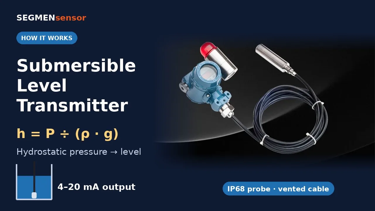
A hydrostatic level sensor is a pressure sensor used to measure liquid level. It sits at the bottom of a tank, sump or borehole (submersible probe) or on a bottom flange, and measures the head pressure of the liquid above it. Level is pressure divided by density and gravity, so a constant-density liquid gives a linear 4–20 mA signal from empty to full. It works regardless of foam, vapour or tank shape, but it needs a known density and an atmospheric reference.
How does a hydrostatic level sensor work, step by step?
The liquid’s weight presses on a diaphragm; the sensing element turns the deflection into an electrical signal; the electronics scale it to level. The diagram shows the four steps.
- Pressure builds with depth. At the probe, the liquid exerts P = ρgh, independent of tank diameter or shape. Units follow the SI definitions published by NIST (SI units: pascal, metre, kilogram) ↗.
- The atmosphere is subtracted. The surface of an open tank carries atmospheric pressure, about 101 kPa — the same as roughly 10 m of water. A vent tube in the cable lets that pressure reach the back of the diaphragm, so the sensor reads gauge pressure only.
- The cell converts pressure. A ceramic (Al₂O₃) or silicon piezoresistive element changes resistance as the diaphragm flexes.
- The electronics scale it. The transmitter outputs 4 mA at the bottom of the range and 20 mA at the top, the analogue current range defined by IEC 60381-1 for direct-current process signals ↗.
What is the hydrostatic level formula? Worked example
h = P ÷ (ρ · g), where h is level above the diaphragm in metres, P the gauge pressure in pascals, ρ the liquid density in kg/m³ and g = 9.80665 m/s² (standard gravity). Because transmitters are calibrated in metres of water column (mWC, ρ = 1000 kg/m³), the practical form is:
true level = indicated mWC ÷ specific gravity (SG)
- Transmitter: 0–10 mWC, 4–20 mA. The PLC reads 12.8 mA.
- Indicated head: (12.8 − 4) ÷ 16 × 10 = 5.5 mWC.
- Liquid is water (SG ≈ 1.0): level = 5.5 m.
- Same reading in a fuel with SG 0.84: level = 5.5 ÷ 0.84 = 6.55 m. Ignoring density would under-read by more than 1 m.
- Pressure at the probe in step 3: 1000 × 9.80665 × 5.5 ≈ 53.9 kPa (0.539 bar, 7.8 psi).
All values above are calculated. Do the same conversion for any liquid with the hydrostatic level calculator, convert mA to level with the 4–20 mA calculator, and switch kPa, bar, psi and mWC with the pressure unit converter.
How much does density change the reading?
Density depends on the liquid and its temperature. The table shows how far a water-calibrated sensor reads from the true level when the column is exactly 5.00 m.
| Liquid (typical density) | Density, kg/m³ | Indicated on 5.00 m column | Error if not corrected |
|---|---|---|---|
| Water, 4 °C | 1000 | 5.00 mWC | 0 |
| Water, 20 °C | 998 | 4.99 mWC | −0.2 % (−9 mm) |
| Water, 80 °C | 972 | 4.86 mWC | −2.8 % (−141 mm) |
| Seawater | ≈ 1025 | 5.13 mWC | +2.5 % (+125 mm) |
| Diesel fuel | ≈ 840 | 4.20 mWC | −16 % (−800 mm) |
Calculated values. Fuel and seawater densities vary by grade and salinity — use the value from your medium’s data sheet and set it as SG in the PLC scaling.
Why does a hydrostatic level reading drift? Causes and fixes
| Symptom | Likely cause | What to do |
|---|---|---|
| Level moves with the weather | Vent tube blocked, kinked or wet; or a sealed (non-vented) sensor in an open tank | Terminate the cable in a vented junction box; fit a desiccant vent plug outdoors |
| Reading low or high by a fixed percentage | Liquid density differs from water | Divide indicated mWC by SG in the PLC |
| Reading jumps during filling or mixing | Probe swings in turbulence or sits in the inlet stream | Hang the probe in a stilling pipe away from inlets |
| Zero offset at “empty” | Diaphragm sits above the tank floor, or sludge covers it | Add the mounting height as an offset; keep the probe clear of sediment |
| Steady 0 mA or below 3.8 mA | Open loop or supply below the minimum | Check wiring and supply (12–36 V DC for SEGMENsensor submersible probes) |
The vent tube is the most common cause of drift. For the difference between vented gauge, sealed gauge and absolute references, see gauge vs absolute vs sealed gauge pressure.
Submersible probe or flange-mounted: which hydrostatic sensor fits?
- Submersible probe — hangs on its cable in wells, boreholes, sumps, reservoirs and open tanks. No tank penetration needed; suits deep installations.
- Bottom- or side-mounted pressure transmitter — screwed into a fitting near the tank bottom. Suits closed process tanks where a cable cannot hang freely; level is measured from the tapping point.
- Pressurised or closed tanks — the gas pressure above the liquid adds to the reading, so a single gauge sensor is not enough; a differential measurement (bottom minus top) is needed. See gauge vs absolute vs differential pressure transmitters.
Comparing hydrostatic with float, ultrasonic and magnetostrictive methods? Use the liquid level sensor selection guide.
SEGMENsensor submersible level transmitter specifications
| Parameter | Value |
|---|---|
| Sensing element | Piezoresistive ceramic / silicon piezo |
| Range | 0–1 mWC to 0–100 mWC (specify at order) |
| Output | 4–20 mA (2-wire) / 0–10 V / 0–5 V |
| Accuracy | ±0.1% FS standard / ±0.05% FS high accuracy |
| Supply | 12–36 V DC |
| Probe / diaphragm | 316L stainless steel / ceramic (Al₂O₃) or 316L |
| Protection | IP68, continuous submersion |
| Cable | PVC vented (standard) or PTFE (chemical media); 5 m standard, up to 50 m |
| Process temperature | −20 °C to +80 °C |
| Samples | From 1 pc for qualification; volume per project |
IP68 is defined in IEC 60529 (degrees of protection by enclosures) ↗; the submersion depth and duration are set by the manufacturer. Full data, installation video and datasheet are on the submersible level transmitter page; all level technologies are on the liquid level sensor page.
Specifying a hydrostatic level sensor for an OEM project?
Send the liquid and its density, maximum depth, temperature, cable length and the PLC input. We will propose the range, diaphragm and cable. Qualification samples in 5–7 working days · production 3–5 weeks · FOB China · reply within 24 hours.
Frequently Asked Questions
A submersible level sensor is one type of hydrostatic level sensor. Both measure the pressure of the liquid column; the submersible version hangs on its cable at the bottom of the tank or well, while other versions mount in a fitting near the tank bottom.
About 9.81 kPa, which is 0.098 bar or 1.42 psi, calculated with a density of 1000 kg/m³ and standard gravity of 9.80665 m/s². A 10 m water column therefore gives about 98 kPa at the sensor.
The vent tube lets atmospheric pressure reach the back of the diaphragm, so the sensor measures only the liquid column. Without it, barometric changes would appear as level changes: 1 kPa of air pressure equals about 10 cm of water.
Yes, if the density is known and stable and the wetted materials suit the liquid. Divide the indicated metres of water column by the specific gravity. A 316L probe with PTFE cable is used for chemical media.
SEGMENsensor submersible level transmitters are ±0.1% FS as standard and ±0.05% FS in the high-accuracy version. On a 0–10 mWC range, ±0.1% FS is ±10 mm. Density and temperature changes of the liquid add to this.
Not with a single gauge sensor, because the gas pressure above the liquid adds to the reading. A pressurised tank needs a differential measurement, subtracting the pressure at the top of the tank from the pressure at the bottom.