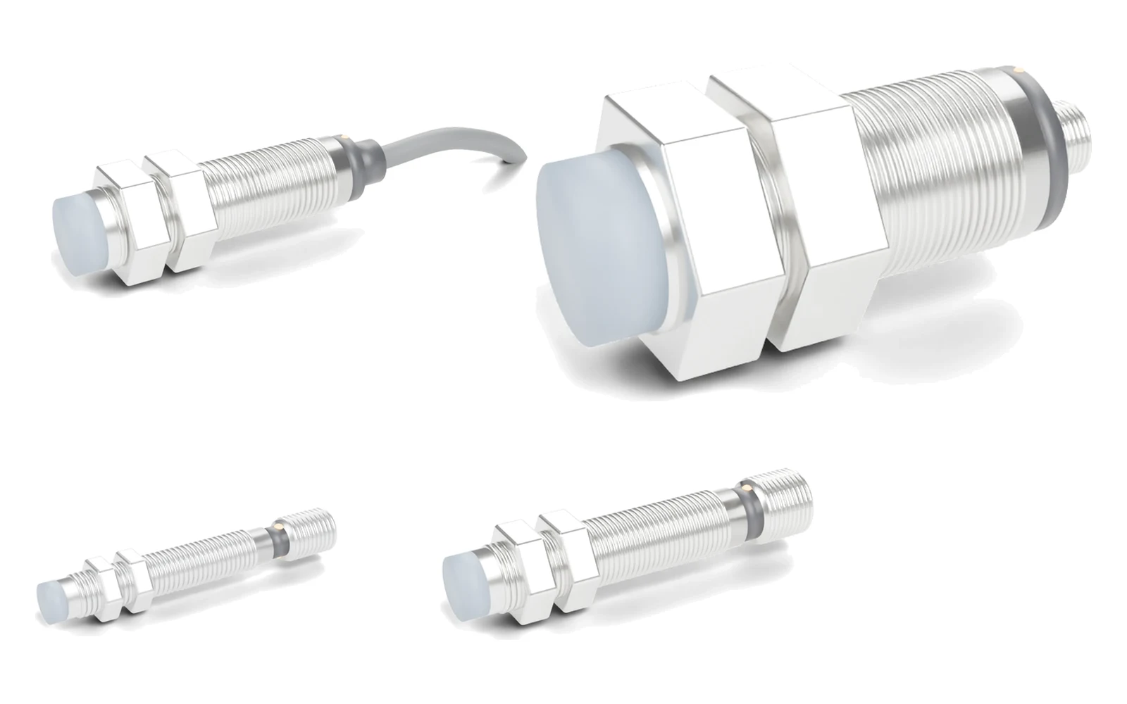
Look at the sensor's LED with the target in front of it. If the LED stays off, the fault is on the sensor side: no supply, a target that is too far away or not metal, or a damaged sensor. If the LED lights but the PLC input stays off, the fault is in the wiring: NPN/PNP does not match the input card, the 0 V common is missing, or a 2-wire sensor's leakage current holds the input. A multimeter on the brown, blue and black wires confirms which.
Safety first: troubleshoot on live 24 V DC circuits only where your site rules allow it, and isolate the machine before reaching into a hazardous area. In the USA, servicing machinery falls under the OSHA lockout/tagout standard (29 CFR 1910.147), linked at the end of this page.
Is it the sensor, the wiring or the target? Start with the LED
The LED on the back of the sensor is driven by the same circuit that drives the output transistor, so it splits the fault in two. The diagram below is the order our applications engineers use when a customer reports a sensor that "does not detect".
How do you test a proximity sensor with a multimeter?
Test it in place with the controller still connected, because an open PNP or NPN output with no load can read a meaningless floating voltage. Set the meter to DC volts and follow these steps.
- Supply. Measure between brown (+) and blue (0 V). On SGI-GP 3-wire models you need 10–30 V DC; DC 2-wire models run on 10–60 V DC.
- Output with no target. Measure between black and blue with nothing in front of the face and note the reading.
- Output with target. Hold a piece of mild steel close to the face (closer than half of Sn) and measure again. The LED should light and the reading should change as in the table below.
- Bench test if in doubt. Disconnect the sensor, power it from a known 24 V DC supply and connect a load between black and the opposite supply rail — a 24 V relay or a resistor (see the worked example below). If the output still does not change with steel on the face, the sensor is faulty.
| Sensor output (NO) | Measure | No target | Target present |
|---|---|---|---|
| PNP (sourcing) | Black to blue | ≈ 0 V | ≈ 21.5–24 V (supply minus ≤ 2.5 V drop) |
| NPN (sinking) | Black to blue | ≈ 24 V (pulled up through the input) | ≈ 0–2.5 V |
| NPN (sinking) | Brown to black | ≈ 0 V | ≈ 21.5–24 V |
On a normally closed (NC) sensor the two columns swap (see NO vs NC sensor outputs). The "target present" voltages are calculated from a 24 V supply and the SGI-GP voltage drop of 2.5 V or less; your input card and cable add their own small drops. Wire colours follow IEC 60947-5-2: brown +, blue 0 V, black output, white second output on 4-wire models — see the NPN vs PNP proximity sensor wiring guide for the circuit diagrams.
Worked example: sizing a load resistor for a bench test or a microcontroller input
A transistor output needs a load to give a clean reading. Choose a resistor that draws a few milliamps:
I = V ÷ R → 24 V ÷ 10 kΩ = 2.4 mA · P = V² ÷ R = 24² ÷ 10 000 = 0.058 W (calculated)
A 10 kΩ, 0.25 W resistor from black to blue (PNP) or from black to brown (NPN) is enough for a meter reading. When a PNP sensor feeds a microcontroller pin, use a voltage divider or an opto-isolated input rather than connecting 24 V to a 3.3 V or 5 V pin; an NPN output with a pull-up resistor to the logic supply is the simpler interface.
Why does the LED light but the PLC input stays off?
Because the sensor is switching but the current cannot flow through the input. These are the causes we see most often, in order of frequency:
| Cause | How to confirm | Fix |
|---|---|---|
| PNP sensor on a sourcing (NPN-type) input, or NPN on a sinking input | Output voltage changes correctly at the sensor, but the input LED never lights | Order the opposite output type or change the input card's common wiring |
| Sensor 0 V not shared with the controller | Measure between sensor blue and the input card common: it should read 0 V | Connect both to the same 0 V reference |
| Wrong input terminal or broken cable core | Measure the voltage at the input terminal itself, not only at the sensor | Repair the cable or connector; check M12 pin 4 = black |
| NC sensor wired where NO was expected | Input is on with no target and turns off when the target arrives | Use the NO output, or invert the logic in the program |
| DC 2-wire sensor leakage current or voltage drop too high for the input | Input flickers or stays on; voltage across the input is never close to 0 V | Check the leakage and minimum load current on the datasheet; add a bleeder resistor or use a 3-wire sensor |
Why does the sensor not detect the target at the rated distance?
Because the rated distance Sn is measured under ideal conditions. IEC 60947-5-2 defines Sn with a 1 mm thick mild steel (Fe 360) square target at room temperature, and only assures switching up to 81% of Sn across the full voltage and temperature range. Every other metal reduces the distance further.
Maximum design gap = 0.81 × Sn × material reduction factor
| Target material | Typical reduction factor | M18 flush, Sn = 8 mm: maximum design gap (calculated) |
|---|---|---|
| Mild steel (Fe 360) | 1.00 | 6.5 mm |
| Stainless steel 304 | 0.65 | 4.2 mm |
| Aluminium | 0.45 | 2.9 mm |
| Copper | 0.30 | 1.9 mm |
Reduction factors are typical values; the full list is in the sensing distance guide (Sn, Sr, Su, Sa). If the target is non-ferrous and the gap cannot shrink, the all-metal SGI-FM series is made for aluminium, stainless steel and copper targets. A target smaller than the sensing face, a thin foil, or a target that stops inside the hysteresis band also gives late or flickering switching — how an inductive proximity sensor works explains why.
How do you test a 2-wire proximity sensor?
A DC 2-wire sensor has no separate supply wire: it powers itself through the load, so it can never be tested without one. Wire it in series with the PLC input (or a 24 V relay coil) and measure the voltage across the input.
- Target present: the input voltage should be the supply minus the sensor's on-state voltage drop (see the datasheet).
- No target: a small leakage current still flows to keep the sensor powered, so the input sees a residual voltage.
Worked example (assumed values, not a SEGMENsensor specification): an off-state leakage of 1 mA into an input with 4.7 kΩ impedance gives 1 mA × 4.7 kΩ = 4.7 V across the input (calculated). If the input card's "off" threshold is lower than that, the input never turns off. A bleeder resistor in parallel with the input lowers the voltage; the cleaner fix is a 3-wire NPN or PNP sensor.
Symptom, cause and fix at a glance
| Symptom | Likely cause | What to do |
|---|---|---|
| Never switches, LED dark | No supply, blown fuse, reversed brown/blue, broken cable | Measure brown–blue at the sensor; check cable and connector |
| Switches on steel, not on the real part | Aluminium, brass, copper or stainless target; target too small | Apply the reduction factor; move closer; use SGI-FM all-metal or a larger housing |
| Worked, then stopped after a crash | Sensing face cracked or sensor pushed back in its bracket | Inspect the face; reset the gap; use a flush type recessed in metal |
| Flickers at end of stroke | Target stops near the switching point inside the hysteresis band | Reduce the gap to 0.81 × Sn × factor or less |
| Switches with no target | Non-flush sensor too close to surrounding metal or a neighbouring sensor | Restore the metal-free zone or use a flush type — see flush vs non-flush |
| Intermittent after washdown or coolant spray | Water or coolant entering a loose connector or damaged cable | Tighten and inspect the M12 connector; SGI-GP housings are IP67, with IP68 optional |
| Drops out near welding | Welding magnetic field disturbs the oscillator; spatter on the face | Use the SGI-WR weld-field immune series (up to 150 mT) |
| Detects at low speed, misses targets at high speed | Target rate above the sensor's switching frequency, or PLC input filter too slow | Calculate rpm × targets ÷ 60 and compare with the rating — see proximity sensor switching frequency |
| Fails only when the machine is hot | Ambient at the sensor above the standard +70 °C rating | Use the SGI-HT high-temperature series (T120 or T150 grade) |
Which SEGMENsensor sensor fixes a recurring detection problem?
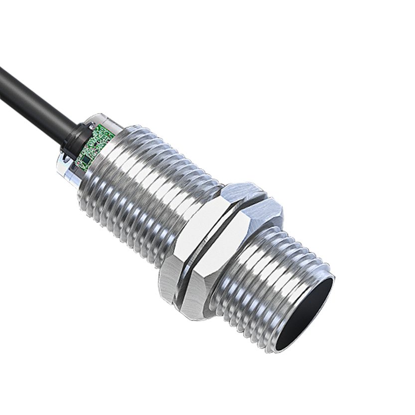
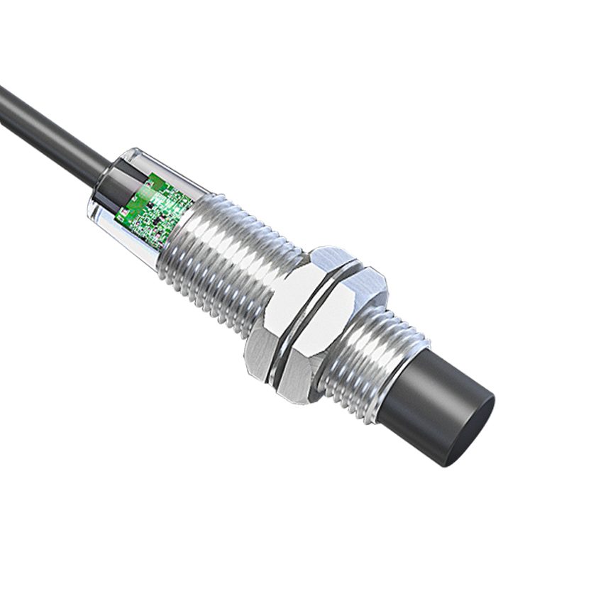
If the same fault keeps returning, the sensor type rather than the individual unit is usually wrong for the job. These series are made for the conditions that most often cause missed detection:
- SGI-GP general-purpose inductive sensors — 6.5 mm to M30, flush or non-flush, Sn from 1 mm to 50 mm, NPN/PNP, NO/NC, DC 2-wire, AC and AC/DC.
- Flush-mount sensors — recess fully into a steel bracket so the face is protected from impact.
- SGI-WR weld-field immune sensors — ignore magnetic fields up to 150 mT in welding cells.
- SGI-HT high-temperature sensors — rated up to +120 °C (T120) or +150 °C (T150) ambient; see the heat-resistant proximity switch selection and troubleshooting guide.
- SGI-HP high-pressure sensors — ceramic face for mounting inside hydraulic cylinders.
- Hydraulic cylinder proximity sensor test and troubleshooting — multimeter steps and a symptom–cause table for proximity switches in hydraulic systems.
Decode the part number on the failed sensor with the proximity sensor part number lookup to confirm its output type, contact and Sn before ordering a replacement.
Sensor keeps missing the target?
Send the part number on the label, the target material and size, the gap, the controller input type and the conditions at the sensor. Our engineers will propose a replacement or a better-suited series. Qualification samples 1–5 pcs in 5–7 working days · FOB China · reply within 24 hours.
Download the inductive proximity sensor datasheet (PDF)
Sensing distance, supply voltage, output types, switching frequency, housing and temperature data for the SEGMENsensor inductive proximity range. Size-specific datasheets are also available for M8, M12, M18 and M30, flush and non-flush. No registration required.
Frequently Asked Questions
Power it with a correct supply (10–30 V DC for SGI-GP 3-wire models), connect a load to the output and hold mild steel against the sensing face. If neither the LED nor the output voltage changes, the sensor is faulty. If the LED changes but the controller does not, the sensor is fine and the wiring or input is the problem.
The output type does not match the input, or the circuit is not complete. A PNP sensor needs a sinking input and an NPN sensor needs a sourcing input, and the sensor's blue wire must share 0 V with the controller. Measure the voltage at the input terminal to find where the signal is lost.
Non-ferrous and stainless targets damp the oscillator less than mild steel, so they switch at a shorter distance. With typical factors of 0.45 for aluminium and 0.65 for stainless steel 304, an M18 flush sensor with Sn = 8 mm assures about 2.9 mm and 4.2 mm respectively (calculated). Move closer or use an all-metal sensor.
No. Only electrically conductive material carries the eddy currents that switch an inductive sensor. For plastic, wood, glass or liquids use a capacitive or photoelectric sensor instead.
The part number on the old sensor or its housing size, the target material and size, the installed gap, flush or non-flush mounting, the controller input type (PNP or NPN, 2-wire or 3-wire) and the conditions at the sensor such as temperature, welding or pressure. Our engineers reply within 24 hours.
Yes. Qualification samples of 1–5 pcs per configuration ship in 5–7 working days. Production lead time and MOQ are confirmed with the quotation. Terms are FOB China with 100% T/T in advance.