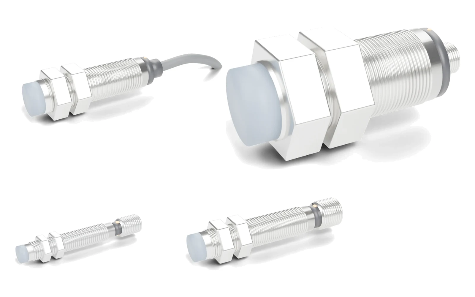
Switching frequency is the speed limit of a proximity sensor's output. Calculate how many targets per second your machine presents (rpm × targets ÷ 60 for rotating parts, speed ÷ target pitch for linear motion) and choose a sensor whose rated frequency is comfortably higher — we size for at least twice the calculated value. Small, flush inductive sensors are the fastest; large non-flush and capacitive sensors are the slowest.
How is proximity sensor switching frequency defined and measured?
Switching frequency is the highest rate at which the output can follow targets that enter and leave the sensing zone, with each pulse still complete. One cycle is one "target present" period (ton) plus one "target absent" period (toff), so:
f = 1 ÷ T = 1 ÷ (ton + toff) → 1 kHz ⇒ T = 1 ms · 200 Hz ⇒ T = 5 ms · 100 Hz ⇒ T = 10 ms
The rating on a datasheet is not measured on your machine. IEC 60947-5-2, the product standard for proximity switches, defines a reference method: standard targets fixed to a rotating non-conductive disc pass the sensing face at half the rated operating distance (½ Sn), with gaps twice the target width. The highest disc speed at which the output still switches for every target is the rated switching frequency. Real targets that are smaller, farther away or made of a weaker material give shorter effective pulses, which is why a margin is needed.
How do you calculate the switching frequency your application needs?
Count the targets that pass the sensor per second. Two formulas cover almost every machine:
| Motion | Required frequency | Symbols |
|---|---|---|
| Rotating (gear, cam, bolt heads on a shaft) | f = n × z ÷ 60 | n = speed in rpm, z = targets per revolution |
| Linear (chain pins, conveyor flights, rack teeth) | f = v ÷ p | v = speed in m/s, p = target pitch in m |
| Maximum speed for a given sensor | nmax = 60 × frated ÷ z | frated = datasheet switching frequency |
Worked example 1: gear-tooth speed sensing
A 20-tooth gear turns at up to 1,500 rpm: f = 1,500 × 20 ÷ 60 = 500 Hz (calculated). Sized at twice the calculated frequency, the sensor needs a rating of 1 kHz or more. An M8 or M12 flush SGI-HT sensor (1 kHz) fits; an M18 flush model (400 Hz) would miss teeth near top speed, even though it has the longer sensing distance.
Worked example 2: check the pulse width as well
The frequency can be fine while each pulse is too short. Pulse width is target width divided by surface speed: ton = w ÷ v. On a 100 mm pitch-diameter gear at 1,500 rpm the surface speed is π × 0.1 × 1,500 ÷ 60 = 7.85 m/s, so a 4 mm wide tooth gives ton = 0.004 ÷ 7.85 ≈ 0.51 ms (calculated). SGI-HT response times are 0.1–1 ms by model, so a model at the slow end of that range would not see the tooth. The PLC input must also be fast enough: set its input filter shorter than ton or use a high-speed counter input.
Worked example 3: slow linear motion
Chain pins at a 25.4 mm pitch moving at 0.5 m/s give f = 0.5 ÷ 0.0254 ≈ 20 Hz (calculated). Every inductive series and even an 80 Hz capacitive sensor has ample margin, so choose on sensing distance, temperature and mounting instead.
Quick calculator: required switching frequency
Enter the shaft speed and the number of targets per revolution.
Required: 500 Hz · choose a sensor rated ≥ 1000 Hz (2× margin)
Why do larger proximity sensors have a lower switching frequency?
A larger housing carries a larger coil to reach a longer sensing distance. The bigger coil and its wider field take longer to be damped and to recover as each target passes, so the evaluation circuit needs more time per cycle. Non-flush models, with their wider field, are slower again. Our published part-number data shows the trend clearly:
| Series | Housing | Mounting · Sn | Switching frequency |
|---|---|---|---|
| SGI-HT high-temperature inductive | M8 | Flush 1–2 mm · non-flush 2–4 mm | 1 kHz |
| SGI-HT | M12 | Flush 2–4 mm | 1 kHz |
| SGI-HT | M12 | Non-flush 4–8 mm | 500–800 Hz |
| SGI-HT | M18 | Flush 5–8 mm | 400 Hz |
| SGI-HT | M18 | Non-flush 8–16 mm | 300 Hz |
| SGI-HT | M30 | Flush 10–16 mm | 200 Hz |
| SGI-HT | M30 | Non-flush 15–25 mm | 150 Hz |
| SGI-WR weld-field immune inductive | M8 / M12 / M18 | Flush and non-flush | 1 kHz / 800 Hz–1 kHz / 500–800 Hz |
| SGI-HP high-pressure inductive | M8 / M12 | Flush, ceramic face | 1 kHz |
| SGC-HT high-temperature capacitive | M8–M30 | Flush and non-flush | 80–100 Hz |
Source: the series pages linked below and the proximity sensor part-number table (CSV). The value for each exact part number is in that table; values for the SGI-HP M18 version are confirmed per project. Capacitive sensors sit well below inductive sensors of the same housing size; for when each type is the right choice, see inductive vs capacitive proximity sensors.
Is switching frequency the same as response time?
No. Response time is the delay between a target arriving and the output changing; switching frequency is how many complete cycles per second the output can produce. Both matter for fast targets.
| Switching frequency | Response time | |
|---|---|---|
| Unit | Hz (cycles per second) | ms |
| Answers | How many targets per second can be counted? | How short can one target pulse be? |
| Check against | n × z ÷ 60 or v ÷ p | Pulse width w ÷ v and the PLC input filter |
| SEGMENsensor examples | SGI-HT 150 Hz–1 kHz · SGC-HT 80–100 Hz | SGI-HT 0.1–1 ms · SGI-WR 0.1–0.5 ms · SGC-HT 1.5 ms |
What happens when the switching frequency is too low?
The counter reads low or the output stops switching. Typical symptoms and fixes:
- Speed reading drops or jumps at high rpm — pulses are being lost. Use a smaller or flush sensor with a higher rating, or fewer, wider targets.
- Output LED stays on above a certain speed — the gaps are shorter than the recovery time. Make the gaps between targets at least twice the target width, as in the test method.
- Counts are lost only on some teeth — the gap varies with runout. Set the gap at or below ½ Sn so every tooth damps the sensor fully; the sensing distance guide explains Sn and Sa.
- The sensor switches on the bench but not at speed — check the PLC input filter and use a high-speed counter input. The proximity sensor troubleshooting guide covers the wiring checks.
Which SEGMENsensor sensors suit fast targets?
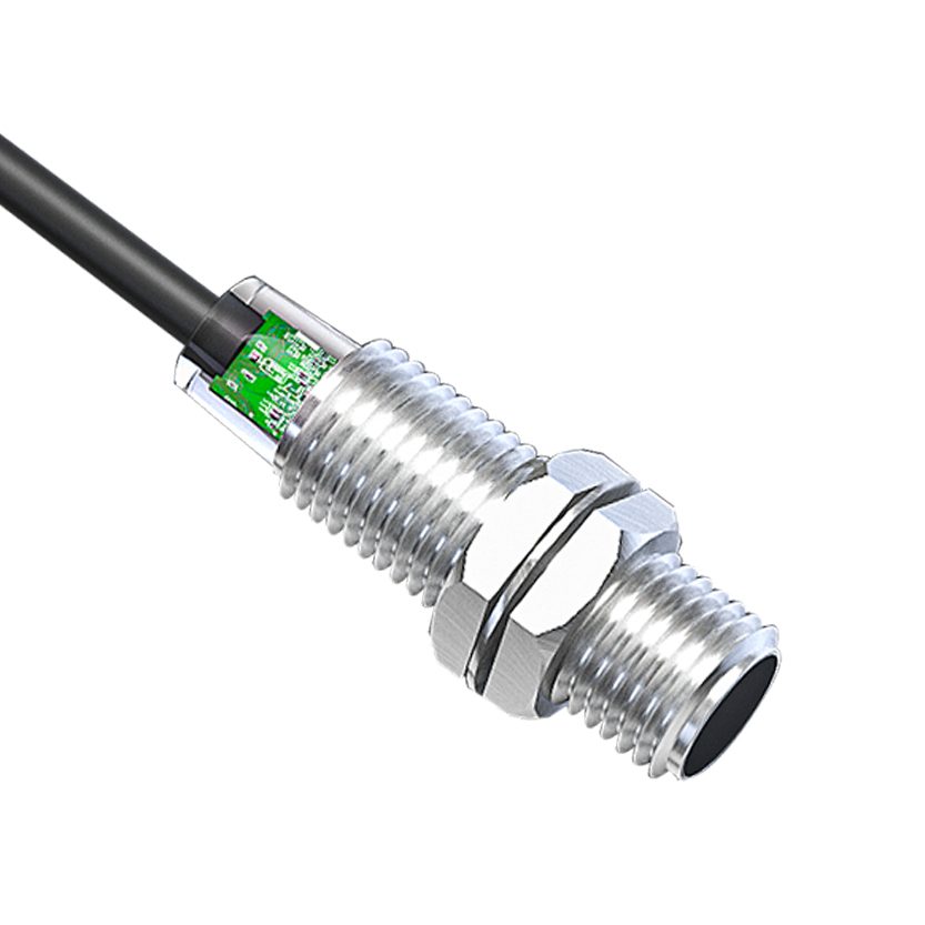
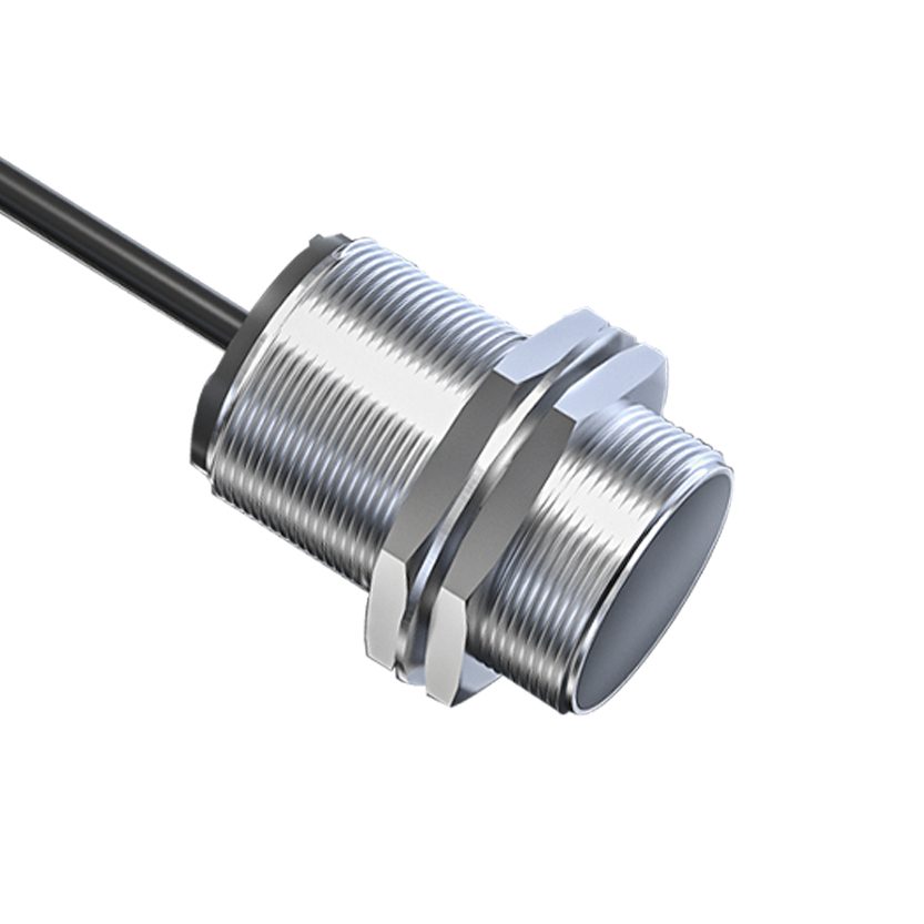
- SGI-GP general-purpose inductive sensors — 6.5 mm to M30, flush or non-flush; switching frequency per part number is given on the datasheet sent with the quotation.
- SGI-HT high-temperature inductive sensors — 150 Hz to 1 kHz by housing, rated up to +120 °C (T120) or +150 °C (T150) ambient.
- SGI-WR weld-field immune sensors — 500 Hz to 1 kHz, immune to magnetic fields up to 150 mT.
- SGI-HP high-pressure sensors — 1 kHz in M8 / M12 for end-of-stroke detection inside hydraulic cylinders.
- SGC-HT high-temperature capacitive sensors — 80–100 Hz, for non-metal targets at moderate speed.
To check the rating of a sensor already on your machine, decode its label with the proximity sensor part number lookup. For how the oscillator and eddy currents work, see how an inductive proximity sensor works.
Need a sensor sized for your speed?
Send the shaft speed or line speed, the number, width and pitch of the targets, the installed gap and the PLC input type. Our engineers will recommend a housing and series. Qualification samples 1–5 pcs in 5–7 working days · FOB China · reply within 24 hours.
Download the inductive proximity sensor datasheet (PDF)
Sensing distance, supply voltage, output types, switching frequency, housing and temperature data for the SEGMENsensor inductive proximity range. Size-specific datasheets are also available for M8, M12, M18 and M30, flush and non-flush. No registration required.
Frequently Asked Questions
The sensor output can switch on and off 1,000 times per second under the IEC 60947-5-2 test conditions, which is one complete cycle every 1 ms. On a 20-tooth gear that corresponds to 3,000 rpm (60 × 1,000 ÷ 20, calculated) before any safety margin.
Multiply the maximum speed in rpm by the number of teeth and divide by 60. A 20-tooth gear at 1,500 rpm needs 500 Hz (calculated). We recommend a sensor rated at least twice that value and a check that each tooth pulse is longer than the sensor response time.
Either the target rate exceeds the sensor's switching frequency, the pulses are shorter than its response time, or the PLC input filter is too slow. Calculate the required frequency, reduce the gap to ½ Sn, and use a high-speed counter input or a smaller flush sensor with a higher rating.
No. SEGMENsensor SGC-HT capacitive sensors are rated 80–100 Hz, while SGI-HT inductive sensors are rated 150 Hz to 1 kHz depending on housing. Use an inductive sensor for fast metal targets and a capacitive sensor for slower non-metal targets.
Usually yes, because longer ranges need larger coils. In the SGI-HT series an M8 flush sensor with 1–2 mm Sn is rated 1 kHz, while an M30 non-flush sensor with 15–25 mm Sn is rated 150 Hz. Choose the smallest housing that still gives a safe gap.
The maximum speed, the number, width and pitch of the targets, the target material, the installed gap, the temperature at the sensor and the PLC input type. Our engineers reply within 24 hours. Qualification samples of 1–5 pcs ship in 5–7 working days; production lead time and MOQ are confirmed with the quotation. Terms are FOB China with 100% T/T in advance.