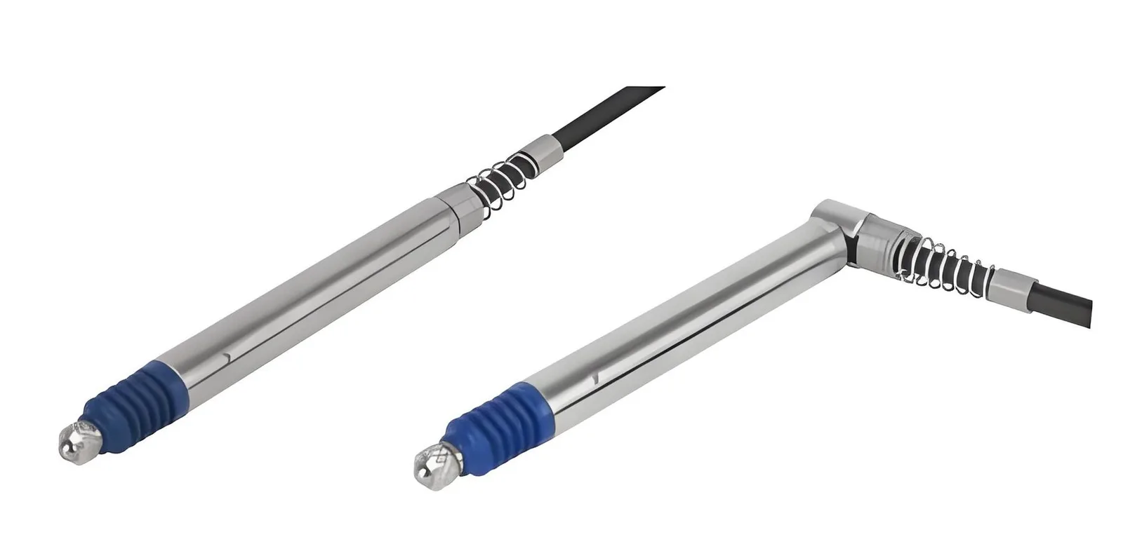
Choose an LVDT for short-to-medium strokes (±0.5–±500 mm), high-temperature environments (up to +200°C), or severe vibration test applications requiring infinite analog resolution. Choose a magnetostrictive sensor for long strokes (up to 7,620 mm), hydraulic cylinder position feedback (up to 350 bar), absolute position output without homing, or digital bus connectivity (Modbus/SSI/CANopen).
How Each Technology Works
LVDT — Linear Variable Differential Transformer
An LVDT displacement sensor contains a primary coil and two secondary coils wound on a hollow cylinder. A ferromagnetic core slides freely inside without mechanical contact. When AC excitation is applied to the primary coil, the mutual inductance between the primary and each secondary varies with core position, producing a differential voltage output that is linearly proportional to displacement. Because the core never touches the coil housing, there is no mechanical wear — the LVDT is inherently a non-contact sensor.
The analog output is continuous and has theoretically infinite resolution, limited only by the signal conditioning electronics. LVDTs tolerate high temperatures well because the measurement principle is electromagnetic — no active electronics are inside the measurement cylinder itself. High-temperature LVDT versions can operate at +200°C or beyond.
Magnetostrictive Sensor — Torsional Ultrasonic Position
A magnetostrictive position sensor operates on a different physical principle. A current pulse travels down a ferromagnetic waveguide wire (the sensing element). Where the pulse's circular magnetic field interacts with the field of a permanent magnet mounted on a float or position magnet, the magnetostrictive effect generates a torsional ultrasonic pulse. This pulse travels back along the waveguide to a pickup coil at the sensor head. The time-of-flight of this return pulse determines absolute position to 0.001 mm resolution.
The key property is absolute position output — the sensor knows its exact position on power-up without any homing motion. The waveguide can be thousands of millimetres long (standard catalogue to 7,620 mm, custom beyond), and multiple position magnets can be tracked simultaneously on a single waveguide.
Side-by-Side Specification Comparison
| Parameter | LVDT | Magnetostrictive |
|---|---|---|
| Measurement principle | Electromagnetic induction (AC) | Torsional ultrasonic (magnetostrictive effect) |
| Stroke range | ±0.5 mm to ±500 mm | 25 mm to 7,620 mm (custom longer) |
| Resolution | Theoretically infinite (analog) | 0.001–0.01 mm (digital) |
| Linearity | ±0.1–0.25% FS ✓ Edge | ±0.05% FS |
| Repeatability | ±0.1% FS | ±0.01% FS ✓ Edge |
| Operating temperature | −55°C to +150°C (std); +200°C (HT) ✓ Edge | −40°C to +85°C |
| Operating pressure | Up to ~100 bar with housing | Up to 350 bar (hydraulic rod type) ✓ Edge |
| Position type | Relative (incremental) | Absolute ✓ Edge |
| Homing on power-up | Required | Not required ✓ Edge |
| Output | AC differential; 4–20 mA / 0–10 V / ±10 V (conditioned) | 4–20 mA / 0–10 V / SSI / CANopen / Modbus / Profibus |
| Update rate | 1–10 kHz (conditioner-dependent) | 1–2 ms (500–1000 Hz) |
| Vibration immunity | Excellent (passive coil) ✓ Edge | Good (electronic head may need damping) |
| Multiple positions / one sensor | No | Yes (up to 4 magnets) ✓ Edge |
| Typical cost | $ (sensor) + $$ (conditioner) | $$ all-in-one |
When to Choose LVDT
LVDT Best for
- Operating temperature above +85°C (engine test benches, furnaces, turbine instrumentation)
- Severe vibration environments where electronic sensor heads are at risk
- Short strokes under ±10 mm requiring sub-micron analog resolution for test-and-measurement DAQ
- Aerospace and defense applications with existing LVDT signal conditioning infrastructure
- Hydraulic valve spool position (short stroke, high frequency response needed)
- Materials testing machines requiring synchronized analog acquisition
LVDT technology has been the standard for precision displacement measurement in aerospace and test-and-measurement for decades. The simple coil-and-core construction is inherently radiation-tolerant and temperature-resistant in ways that electronic sensor heads are not. If your application involves continuous temperatures above +85°C or radiation exposure, LVDT is the correct choice.
When to Choose Magnetostrictive
Magnetostrictive Best for
- Hydraulic cylinder position feedback (rod-style sensors rated to 350 bar)
- Long strokes: injection moulding platens, large actuators, gantry position (500 mm–7,620 mm)
- Liquid level measurement in storage tanks and CDU expansion reservoirs
- Applications requiring absolute position on power-up (machine safety, press control)
- PLC/SCADA integration requiring Modbus RTU, SSI, or CANopen without separate conditioner
- Multiple simultaneous position measurements on a single sensor (up to 4 magnets)
The magnetostrictive principle is now dominant in hydraulic cylinder position sensing because the sensor waveguide can be built directly into the cylinder bore — the position magnet travels with the piston, and there are no external cables or mechanical connections to route. The 350 bar pressure rating covers the full range of industrial hydraulic circuits. Combined with SSI or CANopen output, these sensors integrate directly with modern servo drives without the signal-conditioning stage that LVDT requires.
Application-by-Application Decision Guide
| Application | Recommended Sensor | Key Reason |
|---|---|---|
| Hydraulic cylinder position | Magnetostrictive | 350 bar rated; absolute position; rod-style fits in bore |
| Engine test bench valve stroke | LVDT | High temperature (+150°C+); high vibration; short stroke |
| Injection moulding platen position | Magnetostrictive | Long stroke (up to 2,000 mm); absolute on power-up; SSI output |
| Materials testing (tensile/fatigue) | LVDT | Sub-micron resolution; analog output for DAQ synchronisation |
| CDU expansion tank level | Magnetostrictive | Continuous level; no wetted electronics; Modbus output |
| Industrial robot joint position | Magnetostrictive | Absolute; multi-point; compact rod-style integration |
| Aerospace actuator feedback | LVDT | Existing LVDT ecosystem; radiation/vibration tolerance |
| Storage tank liquid level (large) | Magnetostrictive | Long stroke to 7,620 mm; multiple interface outputs |
Frequently Asked Questions
LVDT sensors use electromagnetic induction — a moving iron core inside a coil — and excel in vibration environments at short-to-medium strokes (±0.5 mm to ±500 mm) with infinite analog resolution. Magnetostrictive sensors use a torsional ultrasonic pulse along a waveguide and deliver absolute digital position over long strokes (25 mm to 7,620 mm) at high operating pressures up to 350 bar. Choose LVDT for harsh-vibration, high-temperature applications; choose magnetostrictive for hydraulic cylinders and absolute position feedback.
Both technologies achieve very high accuracy. LVDT linearity is ±0.1–0.25% FS with theoretically infinite analog resolution. Magnetostrictive resolution is 0.001–0.01 mm with repeatability of ±0.01% FS. For practical industrial applications the accuracy difference is negligible. LVDT has an edge in sub-micron vibration measurement; magnetostrictive has an edge in absolute position retention after power loss.
Yes — magnetostrictive sensors are the preferred choice for hydraulic cylinder position feedback. They are rated for up to 350 bar operating pressure and are built into the cylinder body with the waveguide inside the hydraulic fluid. LVDTs can be used in hydraulic applications but require a separate pressure housing, adding installation complexity. Magnetostrictive sensors output absolute position without homing on power-up, which is critical for machine safety.
LVDT sensors have a wider temperature range: −55°C to +150°C standard, with high-temperature versions to +200°C or beyond, making them suitable for engine test benches and furnace applications. Magnetostrictive sensors typically operate from −40°C to +85°C. For applications above +85°C, LVDT is the safer choice.
No. Magnetostrictive sensors output absolute position — the position value is determined from the travel time of the torsional ultrasonic pulse, independent of previous power state. The sensor reads the correct position immediately on power-up without any homing or calibration cycle. This is a key safety advantage in machine applications.
LVDTs output AC differential voltage natively; signal conditioners convert this to 4–20 mA, 0–10 V, or ±10 V analog. Magnetostrictive sensors output 4–20 mA, 0–10 V, SSI, CANopen, Modbus RTU, or Profibus directly from the sensor head — no separate conditioner required for digital bus versions. For PLC integration, magnetostrictive with Modbus or SSI is simpler; for test-and-measurement DAQ, LVDT analog is preferred.
Both LVDT and magnetostrictive sensors are non-contact and theoretically have unlimited mechanical lifespan — there are no wear surfaces. LVDT lifespan is limited by coil insulation degradation at high temperatures. Magnetostrictive lifespan is limited by the permanent magnet float (typically rated for 10+ years). In practice, both technologies routinely exceed 15–20 years in industrial service.
Use LVDT if: stroke is under ±500 mm, operating temperature exceeds +85°C, the environment has severe vibration, or you need sub-micron analog resolution for test-and-measurement. Use magnetostrictive if: you need stroke above 500 mm, the sensor is inside a hydraulic cylinder (up to 350 bar), you need absolute position on power-up, or you need digital bus output (Modbus/SSI/CANopen) without a separate conditioner.