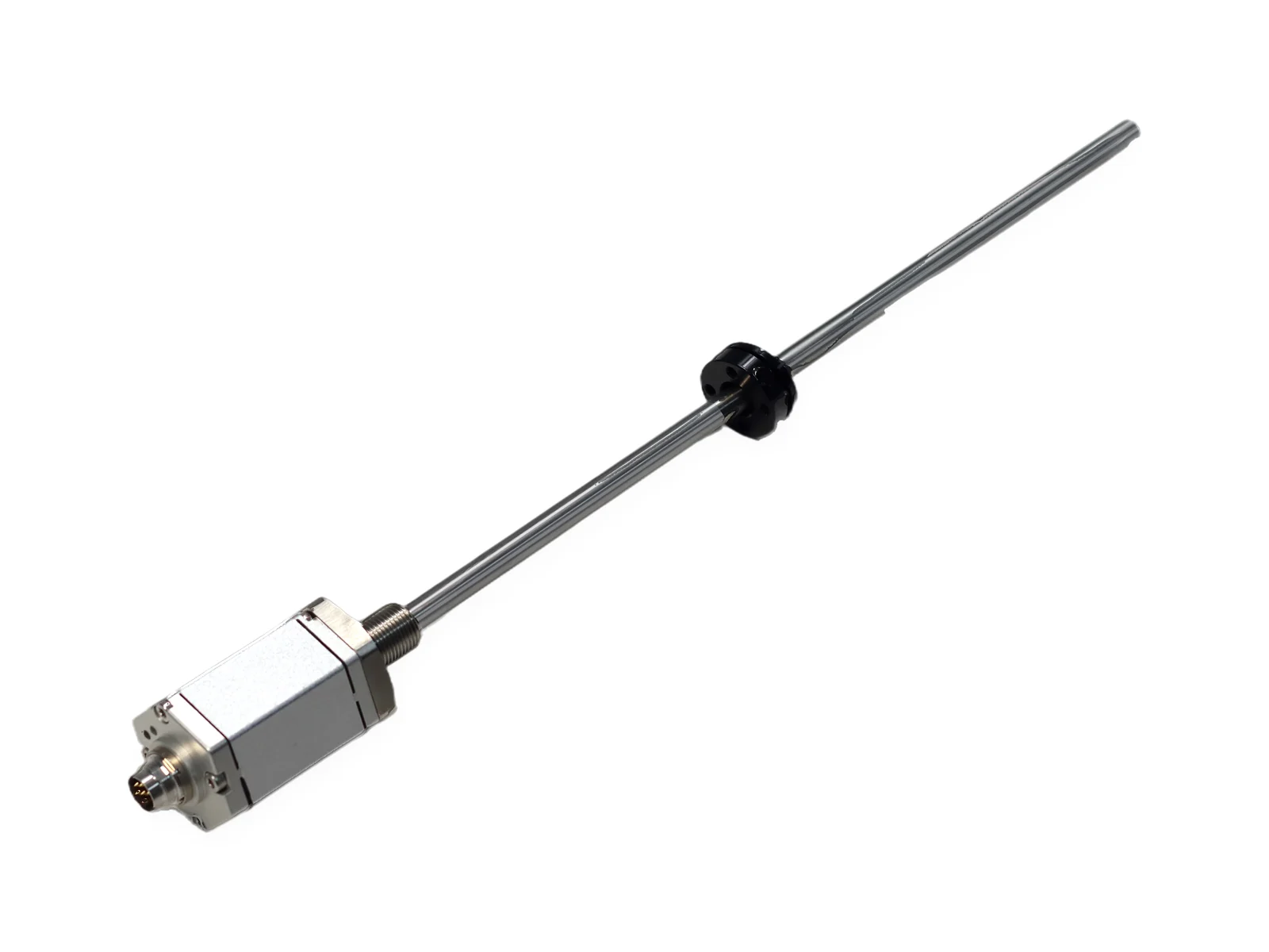
SSI output is a clocked, point-to-point digital output for absolute position. The PLC, servo drive or motion controller is the master: it sends clock pulses, the sensor freezes its current position and shifts it out one bit per clock, most significant bit first. Because every read carries the full absolute value, SSI needs no homing, no addresses and no counting of pulses.
What does SSI output mean on a position sensor?
SSI stands for Synchronous Serial Interface. "Synchronous" means the data bits are timed by a clock that the receiver supplies; "serial" means the position word travels one bit after another on a single pair of wires. Physically, clock and data each use a balanced differential pair of the type defined in EIA/TIA-422-B ↗ (RS-422), which rejects common-mode noise picked up along the cable.
On a linear position sensor such as a magnetostrictive sensor, the electronics measure where the position magnet sits on the waveguide and hold that value as a number of counts. SSI is simply the way this number leaves the sensor. The alternatives are an analog signal (4–20 mA or 0–10 V, compared in the 4–20 mA calculator), a fieldbus such as RS485 Modbus, or industrial Ethernet.
How does an SSI read cycle work, step by step?
Every read follows the same four steps. The diagram shows a short 6-bit word for clarity; real sensors use longer words set in the ordering code.
- Latch. The clock line idles high. At the first falling edge the sensor freezes its current position in a shift register, so all bits of one word belong to the same instant.
- Shift out. On each rising edge the sensor sets the next bit on the data pair, MSB first. An n-bit word needs n + 1 clock pulses.
- Monoflop time. After the last pulse the data line stays low for a short, fixed time (the monoflop time, given in the datasheet). If the controller clocks again inside this window, it re-reads the same word.
- Ready. The data line returns high and the next read starts with a new latch.
How do word length, resolution and code fit together?
Three settings must match between the sensor and the controller. On SEGMENsensor magnetostrictive sensors they are fixed in the SSI part of the ordering code: SS25G005F means a 25-bit word, Gray code (G) and 5 µm per count, with the last letter setting the counting direction as described in the SGM-PR10 datasheet.
| Setting | What it fixes | Formula / example (calculated values) |
|---|---|---|
| Word length n | Number of bits per read | Largest count = 2n − 1; 25 bits → 33,554,431 counts |
| Resolution | Length of one count | Position = counts × resolution; 250,000 counts × 5 µm = 1,250 mm |
| Covered range | Longest position the word can express | 2n × resolution; 25 bit × 5 µm ≈ 167.8 m; 24 bit × 1 µm ≈ 16.8 m |
| Code | How the count is encoded | Gray (1 bit changes per step) or binary (plain integer) |
| Read time | Time the clock burst occupies | (n + 1) ÷ fclock; 26 pulses at 100 kHz = 260 µs, at 500 kHz = 52 µs, at 1 MHz = 26 µs |
Resolution is the size of one count, not the accuracy. Measurement quality comes from the sensor itself: on SGM-PR10 and SGM-PE10 non-linearity is below ±0.01% FS (min. ±50 µm) and repeatability below ±0.001% FS (min. ±5 µm).
Worked example: converting a Gray-code word to binary
Gray code is defined so that only one bit changes from one value to the next (NIST Dictionary of Algorithms and Data Structures ↗). To decode it, keep the MSB, then XOR each following Gray bit with the binary bit just found.
| Count | Binary | Gray | Bits that change from the previous count (Gray) |
|---|---|---|---|
| 3 | 011 | 010 | 1 |
| 4 | 100 | 110 | 1 (binary changes 3 bits here) |
| 5 | 101 | 111 | 1 |
| 6 | 110 | 101 | 1 |
Example: Gray word 0110 → b3 = 0; b2 = 0 XOR 1 = 1; b1 = 1 XOR 1 = 0; b0 = 0 XOR 0 = 0 → binary 0100 = count 4. In binary, the step from 3 to 4 changes three bits at once; if the sensor were read during that step, the controller could see any of eight values. With Gray code the worst case is an error of one count.
How long can an SSI cable be?
The limit is set by delay. The sensor answers each clock edge after the signal has travelled down the cable and back. With a typical propagation delay of about 5 ns per metre of twisted-pair cable, the round trip adds 10 ns per metre (calculated values):
| Cable length | Round-trip delay | Half clock period at 500 kHz (1 µs) | Half clock period at 1 MHz (0.5 µs) |
|---|---|---|---|
| 10 m | 0.1 µs | 10% of window | 20% of window |
| 50 m | 0.5 µs | 50% of window | 100% — bits shift |
| 100 m | 1.0 µs | 100% — bits shift | 200% — bits shift |
So longer cables need lower clock frequencies, unless the controller offers delay compensation. Always take the final limit from the controller manual and the sensor datasheet. Use shielded twisted pairs with clock and data in separate pairs, ground the shield at one end, and route the cable away from motor and welding leads; industrial sites are expected to meet the immunity levels of IEC 61000-6-2 ↗.
How is an SSI position sensor wired?
An SSI sensor needs six conductors: clock +/−, data +/− and supply +/GND. The 7-pin SSI connector on SEGMENsensor SGM-PR10 and SGM-PE10 sensors is assigned as follows (analog and RS485 versions use a 6-pin connector):
| Pin | Signal | Connect to |
|---|---|---|
| 1 | (−) Data | Controller data input − |
| 2 | (+) Data | Controller data input + |
| 3 | (+) Clock | Controller clock output + |
| 4 | (−) Clock | Controller clock output − |
| 5 | Input power + | 24 V DC ±20% (standard) |
| 6 | Input power − (GND) | 0 V |
| 7 | NC | Not connected |
In the controller, set the encoder type to SSI and enter the same word length, code, resolution and direction as the ordering code.
When should I choose SSI instead of an analog or RS485 output?
| Need | Better choice | Why |
|---|---|---|
| Closed-loop servo axis on a drive with an SSI encoder port | SSI | Absolute digital value, fixed read time, no A/D conversion or scaling drift |
| Simple PLC monitoring or a panel display | 4–20 mA or 0–10 V | Any analog input works; check the loop with the loop resistance calculator |
| Several sensors on one cable | RS485 Modbus RTU | Addressable multi-drop bus; SSI is one sensor per input |
| Long cable in a noisy plant with a slow loop | SSI at low clock, or 4–20 mA | Differential digital lines or current loop both tolerate long runs |
The read time is rarely the bottleneck: a 26 µs SSI read is short compared with the 1–5 ms sensor update time of a 1–4 m magnetostrictive sensor. Reading faster than the update time just returns the same value again. The LVDT vs magnetostrictive comparison covers when another sensing principle fits better.
Why does an SSI position read wrong? Symptom, cause, fix
| Symptom | Likely cause | What to do |
|---|---|---|
| Value jumps by large steps near certain positions | Gray word read as binary (or the reverse) | Set the controller code to match the ordering code (G = Gray) |
| Value is about twice or half the real position | Word length or bit alignment differs by one bit | Enter the exact word length; check for a leading or trailing status bit setting |
| Position counts the wrong way | Counting direction | Change direction in the controller or order the opposite direction code |
| Random single-read errors, worse with long cable | Clock too fast for the cable, shield or ground fault | Lower the clock frequency; check twisted pairs and one-end shield grounding |
| Constant maximum or zero value | Magnet outside the effective range, or no supply | Check the sensor LED and the 24 V supply on pins 5 and 6 |
SEGMENsensor sensors with SSI output
| Series | Type | SSI | Key data |
|---|---|---|---|
| SGM-PR10 | In-cylinder rod | Standard | 25–8000 mm; rod 35 MPa continuous, 70 MPa peak; IP67 |
| SGM-PE10 | External profile | Standard | 25–8000 mm; IP67 |
| SGM-PR20 | Stainless rod, IP68 | On request | 25–7500 mm |
| SGM-PF10 | Flat head | On request | 25–8000 mm |
| Samples | Samples 1–5 pcs for qualification in 5–7 working days; volume and lead time confirmed with the quotation | ||
All SSI options, the full specification and the datasheet download are on the SSI magnetostrictive position sensor page.
Need SSI settings checked against your controller?
Send the controller or drive model, stroke, required resolution, cable length and supply voltage. Our engineers will propose the SSI ordering code. Qualification samples 1–5 pcs in 5–7 working days · FOB China · 100% T/T in advance · reply within 24 hours.
Frequently Asked Questions
No. RS-422 (EIA/TIA-422) defines only the electrical layer: balanced differential drivers and receivers. SSI is the protocol on top of it: the controller sends a clock burst and the sensor shifts out its position word. Most SSI sensors and inputs use RS-422-type differential lines for clock and data.
Absolute. Every SSI read returns the full position word, so the controller knows the position immediately after power-up without a homing run. An incremental encoder only sends pulses and loses its count when power is removed.
No. SSI is point-to-point: one sensor per controller input, with no addresses. For several axes, use one SSI input per sensor, or choose a bus output such as RS485 Modbus or an industrial Ethernet interface.
Use the highest frequency that the sensor, the controller and the cable length all allow, as given in their datasheets. As a rule, the longer the cable, the lower the clock: at about 5 ns per metre, a 100 m cable adds about 1 µs of round-trip delay (calculated value), which is a full bit time at 1 MHz.
The usual causes are a code mismatch (Gray read as binary or the reverse), a different word length or bit alignment in the controller, a clock too fast for the cable length, or a missing or double-grounded shield. Check the controller settings against the sensor ordering code first.
SSI is a standard output on the SGM-PR10 in-cylinder and SGM-PE10 profile magnetostrictive sensors (25–8000 mm), and available on request on SGM-PR20 and SGM-PF10. Word length, Gray or binary code, resolution and direction are set in the ordering code, for example SS25G005F.