SGM-PE10 Magnetostrictive Linear Position Sensor — External Aluminium Profile, 25–8000 mm
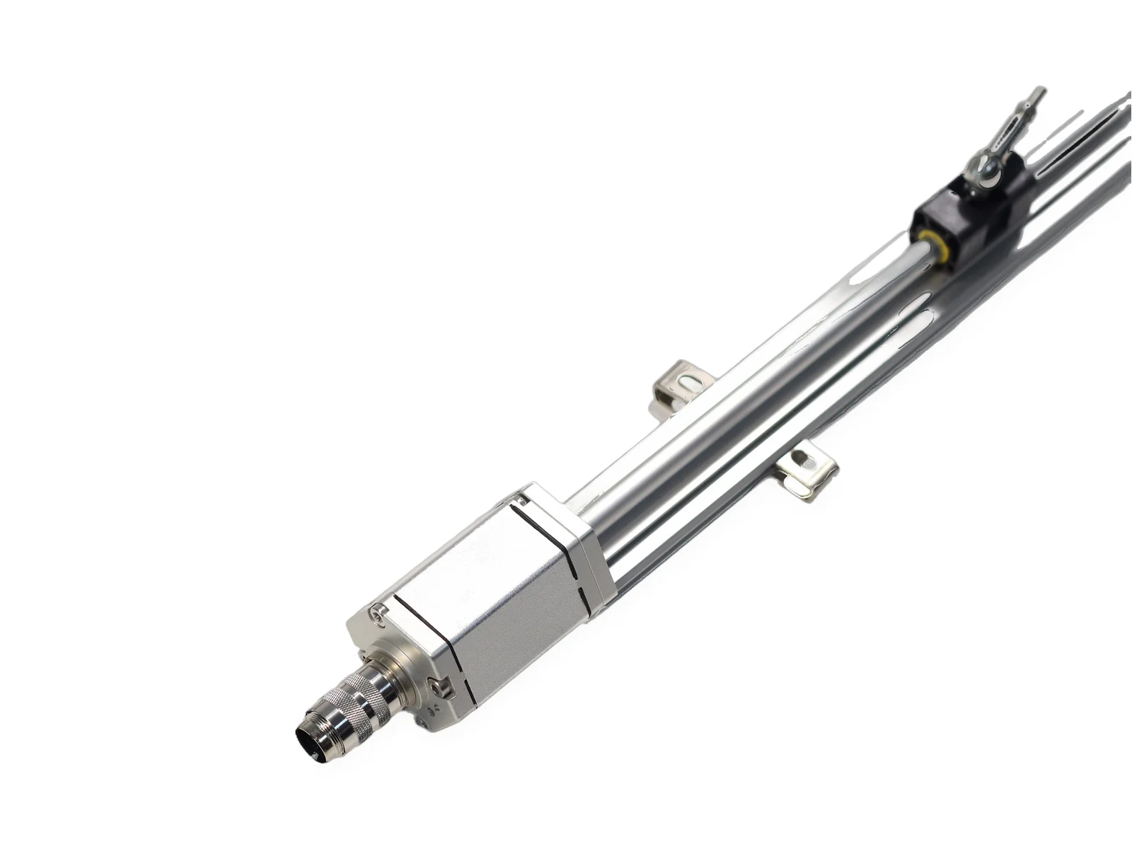
SGM-PE10 is an external magnetostrictive linear position sensor in an aluminium profile housing. It mounts on the machine surface with clamps, measures 25–8000 mm with a slider, trapezoid or floating magnet, and outputs 4–20 mA, 0–10 V, RS485 or SSI with non-linearity below ±0.01% FS.
SEGMENsensor SGM-PE10 is an external magnetostrictive linear position sensor in an aluminium profile housing. It clamps onto the machine surface, reads a slider, trapezoid or floating magnet without contact over 25–8000 mm, and outputs absolute position as 4–20 mA, 0–10 V, RS485 Modbus RTU or SSI.
Measuring range is 25–8000 mm with non-linearity below ±0.01% FS (min. ±50 µm).
Update time is 1 ms for 1–2 m ranges, 2 ms for 2–3 m and 5 ms for 3–4 m.
Supply is 24 V DC (±20%) (standard; 12 V and 5 V ranges depending on output and model) with reverse-polarity protection to -30 V DC and over-voltage protection to 36 V DC.
Protection class is IP67 and operating temperature is -40 to +85 °C.
Qualification samples of 1–5 pcs ship in 5–7 working days, and every RFQ is answered within 24 hours.
Last updated · SEGMENsensor Engineering Team
Watch: how magnetostrictive position sensors work and how ours are tested
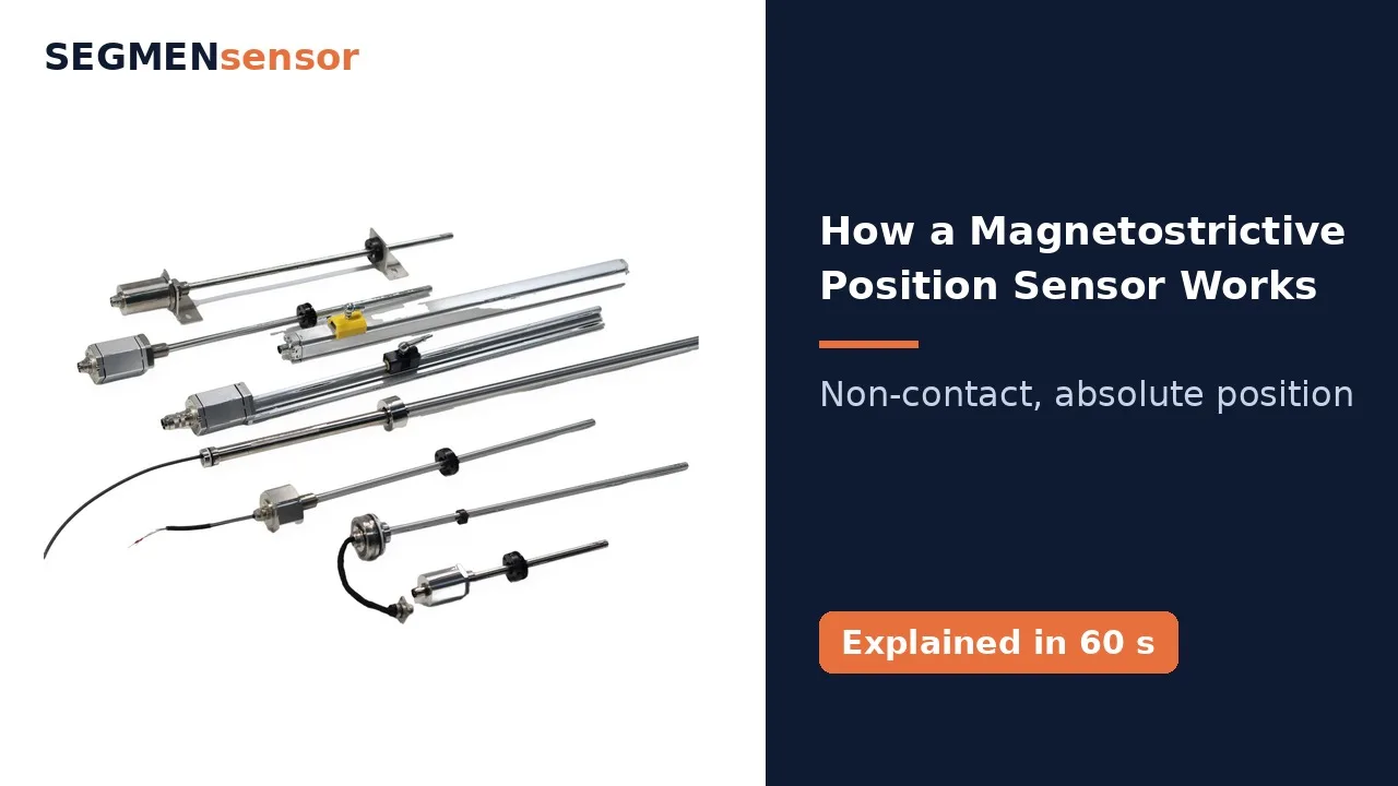
How a Magnetostrictive Position Sensor WorksOne-minute animation of the magnetostrictive time-of-flight principle: current pulse, Wiedemann-effect twist at the position magnet, torsional wave back to the head, position = wave speed × time.
How does a magnetostrictive sensor measure position without contact? Inside the stainless steel rod runs a thin waveguide wire. A ring magnet moves with the piston, the float, or the carriage. First, the electronics send a short current pulse along the wire. The pulse creates a circular magnetic field. Where that field meets the field of the magnet, the wire twists. This is the Wiedemann effect. The twist travels back to the head as a torsional wave, at about two thousand eight hundred metres per second, while a timer measures the travel time. Position equals wave speed times time. The result is absolute position, with no contact and no wear. SEGMENsensor magnetostrictive sensors cover strokes from twenty-five to eight thousand millimetres. Learn more at segmensensor.com.
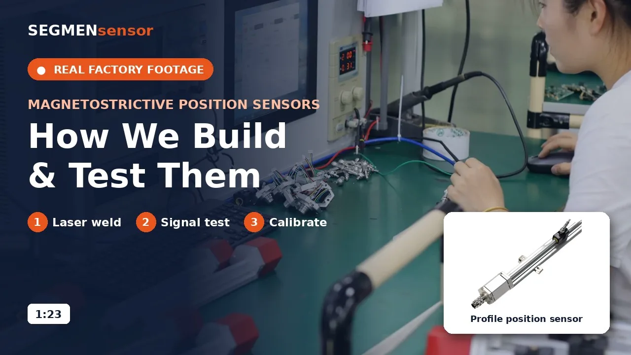
Magnetostrictive Position Sensors: Production and TestingReal production footage of SEGMENsensor magnetostrictive position sensors: electronics assembly, laser welding of rods and flanges, burn-in, signal test on an oscilloscope, calibration on a linear test bench and laser-marked nameplates.
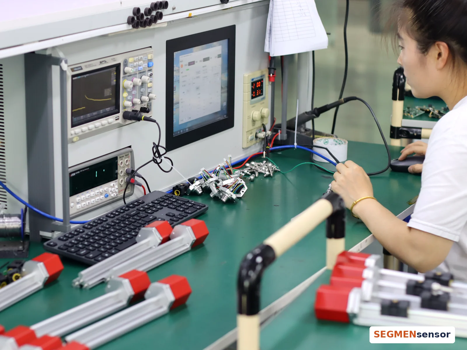
Magnetostrictive position sensors: how SEGMENsensor builds and tests them. It starts with the electronics. Each sensor board is soldered by hand and fitted into the sensor head. The head, cable and connector are assembled on the housing, and heat-shrink sleeves seal the wiring. Rods and flanges are joined by laser welding on a rotary fixture, with a camera to align each seam. The electronics then run on a burn-in rack. Every sensor is tested. The oscilloscope checks the return signal, and a meter checks the output. Each sensor is then calibrated on a linear test bench, where software checks its reading along the stroke. Finally, the nameplate is laser-marked with the model and the company name. Strokes 25–8000 mm · OEM volume supply · Request a quote at segmensensor.com
What is SGM-PE10?
The SGM-PE10 aluminum profile housing is convenient for installation on machine surfaces or in external spaces. Analog output 0-10VDC / 4-20mA / 0-20mA; digital output RS485 / SSI / Profinet (on request). Part number prefix SGM stands for the SEGMENsensor magnetostrictive range; the full ordering code is explained below and in the datasheet.
Updated 2026-10-01 · Values from the SGM-PE10 datasheet, Rev A.
Specifications
SGM-PE10 Specifications
All values from the SGM-PE10 datasheet. Orderable range as listed; longer ranges and special temperature or pressure versions on request.
Need a 3D model or help confirming the right model? Contact our engineers — reply within 24 hours on working days. 3D models (STEP) available on request.
Dimensions & Wiring
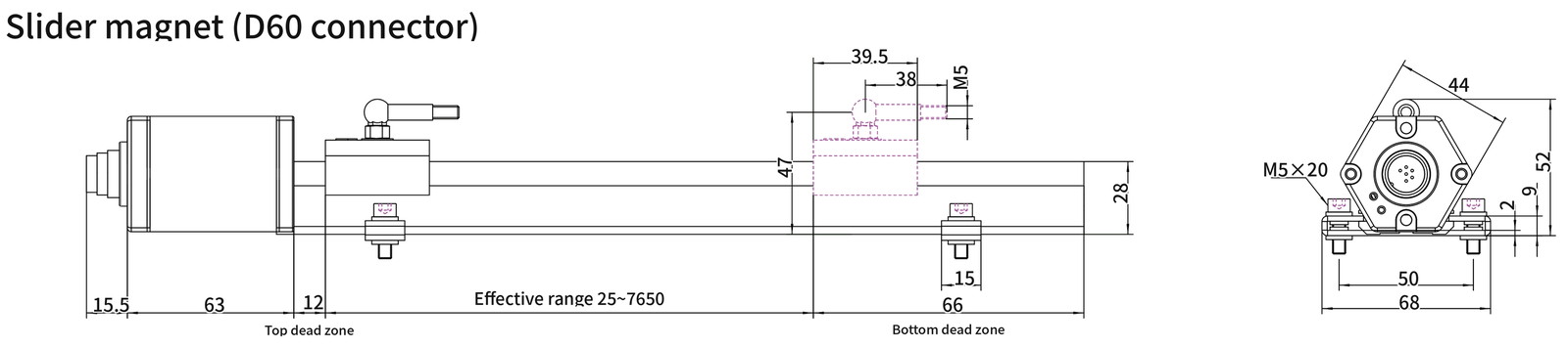
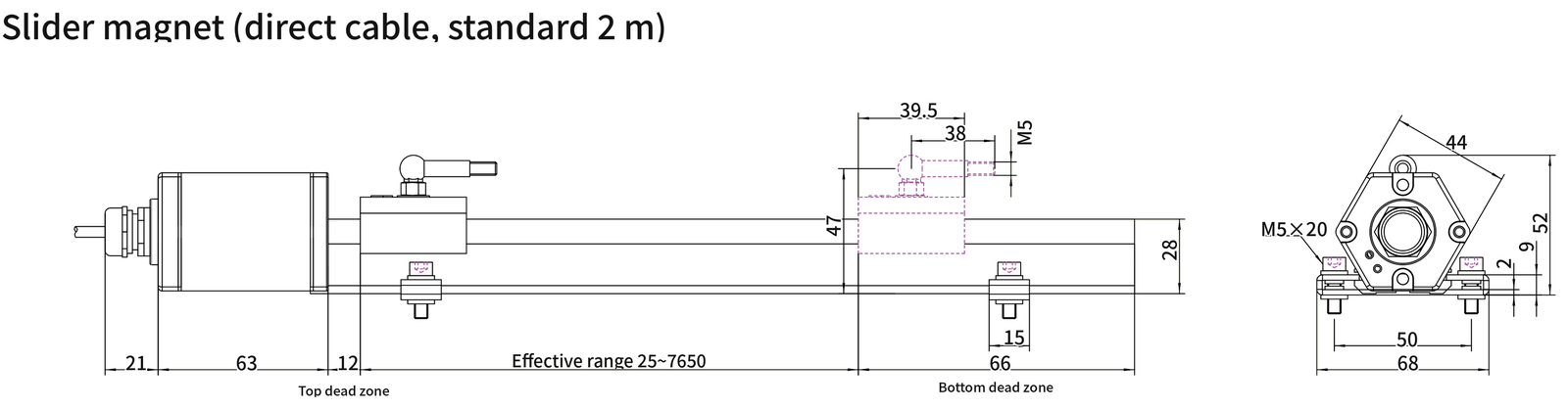
SGM-PE10 Dimensions and Electrical Connection
SGM-PE10 dimensions in mm. Range figures in drawings are illustrative; the orderable range is given in the specification table.
Main dimensions (mm), read from the drawing above
Dimension
Value (mm)
Connector length
15.5
Head length
63
Top dead zone
12
Bottom dead zone
66
Slider magnet arm thread
M5
Height incl. slider magnet
47
Profile height
28
Head width
44
Head height
52
Mounting clamp width
15
Clamp screw
M5×20
Clamp hole spacing
50
Clamp overall width
68
SGM-PE10 dimensions in mm. Range figures in drawings are illustrative; the orderable range is given in the specification table.
Main dimensions (mm), read from the drawing above
Dimension
Value (mm)
Cable gland length
21
Head length
63
Top dead zone
12
Bottom dead zone
66
Slider magnet arm thread
M5
Height incl. slider magnet
47
Profile height
28
Head width
44
Head height
52
Mounting clamp width
15
Clamp screw
M5×20
Clamp hole spacing
50
Clamp overall width
68
Analog connector pinout (6-pin)
1
Analog output +
2
Analog output -
3
Reserved for debugging
4
Reserved for debugging
5
Input power +
6
Input power - (GND)
SSI connector pinout (7-pin)
1
(-)data
2
(+)data
3
(+) Clock
4
(-) Clock
5
Input power +
6
Input power - (GND)
7
NC suspended
LED status indication
Green on / red off
Normal operation within the effective range
Green off / red on
The magnet is out of the effective measurement range or the magnet cannot be detected.
Green off / red flashing
Enter debugging
Ordering Code
How to Order SGM-PE10
Build the part number field by field. Outputs or options listed in the specifications but not in the ordering code are available on request.
Mould, ejector and injection-unit position on the machine frame without drilling a cylinder.
Woodworking and packaging axes
Non-contact, wear-free feedback on long linear axes where potentiometers wear out.
Retrofits
Bolt-on replacement of an external sensor on an existing machine; the floating magnet tolerates small alignment errors.
Sourcing
Ordering SGM-PE10 from SEGMENsensor
1–5 pcsSamples; MOQ confirmed with the quotation
5–7 working daysSample lead time
Per quotationProduction lead time
24 h replyEvery RFQ answered by an engineer
Send the part number, or the stroke, output, mounting and connection you need. Custom ranges, dead zones, cables and magnets are quoted on request.
Magnetostrictive sensors under production testing at the SEGMENsensor factory.
FAQ
SGM-PE10 — Frequently Asked Questions
Slider magnet or floating magnet — which should I choose for SGM-PE10?
A slider magnet runs in the profile groove and is driven by a ball-joint arm, which suits long axes with some misalignment. A floating magnet has no contact with the housing, so there is no wear at all; it needs a controlled air gap. Both are selected in the ordering code.
What is the difference between SGM-PE10 and SGM-PE20?
Both are external profile sensors. SGM-PE10 covers 25–8000 mm and offers SSI; SGM-PE20 is a slimmer profile for 25–4000 mm with analog, dual-channel analog or RS485 output.
What is the measuring range of SGM-PE10?
SGM-PE10 is orderable from 25 to 8000 mm in 5 mm steps. Longer ranges and special temperature or pressure versions are available on request.
How do I read the SGM-PE10 ordering code?
The code follows SGM-PE10-<mounting>-<range>-<output>-<connection>[-options]. For example SGM-PE10-MS-01200-I1F-C02 means: Profile type, slider magnet, 1200 mm, 4–20 mA, 2 m cable. The full option list is in the ordering-code table on this page and in the datasheet.
What is the MOQ and lead time for SGM-PE10?
Qualification samples of 1–5 pcs ship in 5–7 working days, production lead time and MOQ are confirmed with the quotation, and we reply to every RFQ within 24 hours.
Need SGM-PE10 for Your Project?
Send the part number or your application details — an engineer replies within 24 hours on working days with a quotation, lead time and the datasheet.