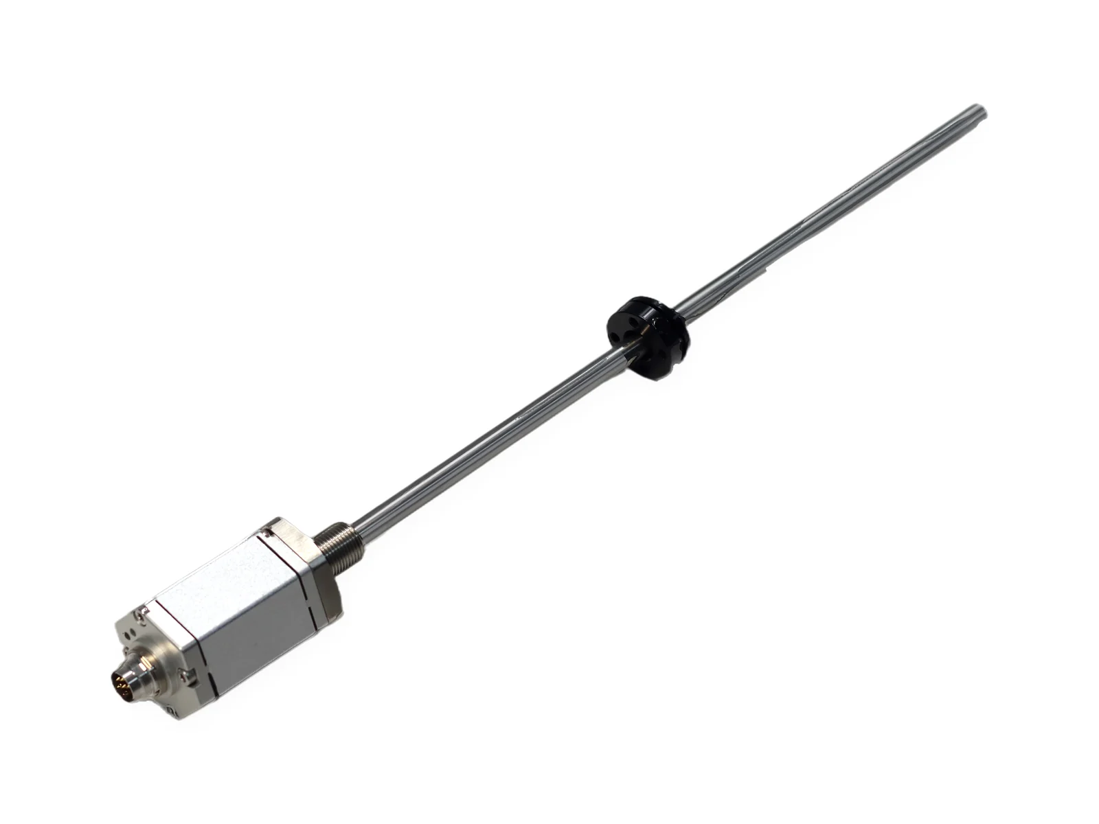
SSI Magnetostrictive Linear Position Sensor — SGM-PR10 / SGM-PE10, 25–8000 mm, OEM China
SEGMENsensor SSI magnetostrictive position sensors provide absolute linear position output via the industry-standard SSI (Synchronous Serial Interface) protocol. SSI is a standard output on the in-cylinder SGM-PR10 and the profile SGM-PE10, and available on request on SGM-PR20 and SGM-PF10. Word length, Gray or binary code and resolution are set in the ordering code (e.g. SS25G005F). Range 25–8000 mm, non-linearity <±0.01% FS, repeatability <±0.001% FS. CE certified, OEM from Shenzhen since 2019, OEM volume supply.
A SEGMENsensor SSI magnetostrictive position sensor sends absolute linear position as a synchronous serial (SSI) Gray or binary code word, so a servo drive or motion controller reads position directly without homing. SSI is standard on SGM-PR10 and SGM-PE10, which cover 25–8000 mm, and available on request on SGM-PR20 and SGM-PF10.
Measuring range is 25–8000 mm on SGM-PR10, SGM-PE10 and SGM-PF10, and 25–7500 mm on SGM-PR20.
Word length, Gray or binary code, resolution and direction are set in the ordering code, for example SS25G005F.
Non-linearity is below ±0.01% FS (min. ±50 µm).
Update time is 1 ms for 1–2 m, 2 ms for 2–3 m and 5 ms for 3–4 m ranges.
Supply is 24 V DC ±20% (standard; 12 V and 5 V ranges depending on output and model) with current consumption below 60 mA; qualification samples are 1–5 pcs.
Last updated · SEGMENsensor Engineering Team
Watch: how our magnetostrictive sensors are built and tested
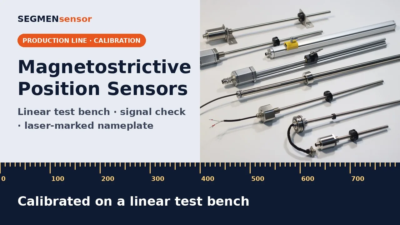
Magnetostrictive Position Sensors: Production and TestingReal production footage of SEGMENsensor magnetostrictive position sensors: electronics assembly, laser welding of rods and flanges, burn-in, signal test on an oscilloscope, calibration on a linear test bench and laser-marked nameplates.
Magnetostrictive position sensors: how SEGMENsensor builds and tests them. It starts with the electronics. Each sensor board is soldered by hand and fitted into the sensor head. The head, cable and connector are assembled on the housing, and heat-shrink sleeves seal the wiring. Rods and flanges are joined by laser welding on a rotary fixture, with a camera to align each seam. The electronics then run on a burn-in rack. Every sensor is tested. The oscilloscope checks the return signal, and a meter checks the output. Each sensor is then calibrated on a linear test bench, where software checks its reading along the stroke. Finally, the nameplate is laser-marked with the model and the company name. Strokes 25–8000 mm · OEM volume supply · Request a quote at segmensensor.com
Magnetostrictive Position Sensors: Testing, Calibration and Laser MarkingProduction-line footage of SEGMENsensor magnetostrictive position sensors: electronics burn-in, wiring and an oscilloscope signal check, calibration on a linear test bench with software, and a laser-marked nameplate.
Magnetostrictive position sensors: testing, calibration and marking. Electronics boards are aged on burn-in racks before assembly. Each sensor is then wired up for testing. The return signal is checked on an oscilloscope. On a linear test bench, the magnet moves along the rod, and the output is calibrated against its position. Calibration values are set and recorded in software. Finally, each nameplate is laser-marked with the model and the company details. Every sensor tested · OEM volume supply. Request a quote at segmensensor.com.
What is an SSI Magnetostrictive Position Sensor?
An SSI magnetostrictive position sensor combines the absolute, non-contact magnetostrictive sensing principle with SSI (Synchronous Serial Interface) digital output. The sensor measures the absolute position of a position magnet along a stainless steel waveguide rod using torsional ultrasonic pulses — no homing required after power-up. The SSI output transmits this position as a binary or Gray code word over differential clock and data pairs; word length and resolution are set in the ordering code. The master (servo drive or PLC SSI module) provides the clock; the sensor returns the data synchronously. On SEGMENsensor, SSI is standard on SGM-PR10 and SGM-PE10.
Technical Specifications
SSI Magnetostrictive Position Sensor — Full Specifications
Values from the SGM-PR10 / SGM-PE10 datasheet. For the full table and ordering code see the SGM-PR10 and SGM-PE10 pages.
Parameter
Value
Measurement Principle
Magnetostrictive, absolute, non-contact
Series with SSI
SGM-PR10 (in-cylinder) and SGM-PE10 (profile) — standard; SGM-PR20 and SGM-PF10 — on request
SSI Settings
Word length, Gray / binary code, resolution (µm) and counting direction set in the ordering code, e.g. SS25G005F
25–8000 mm (SGM-PR10, SGM-PE10, SGM-PF10); 25–7500 mm (SGM-PR20)
Non-Linearity
<±0.01% FS (min ±50 µm)
Repeatability
<±0.001% FS (min ±5 µm)
Update Time
1 ms (1–2 m), 2 ms (2–3 m), 5 ms (3–4 m), <10 ms depending on range
Supply Voltage
24 V DC ±20% (standard; 12 V and 5 V ranges depending on output and model)
Current Consumption
<60 mA (varies with range)
Sensor Head / Tube
Aluminium alloy head, 304 stainless-steel tube and flange (SGM-PR10)
Pressure Rating
35 MPa continuous, 70 MPa peak (SGM-PR10 rod)
Connection
M16 connector (SSI 7-pin) or direct cable
Operating Temperature
-40°C to +85°C
Protection
IP67 (SGM-PR10 / SGM-PE10)
Samples
Samples 1–5 pcs for qualification; volume per project
Lead Time
Confirmed with the quotation
Certifications
CE, RoHS
Download the magnetostrictive position sensor datasheet (PDF)
SGM-PR10 / SGM-PE10 datasheet: 25–8000 mm, analog, RS485 and SSI outputs, non-linearity and repeatability, supply, connectors, rod pressure rating, dimensions and the ordering code. No registration required.
Understanding the SSI protocol ensures correct integration with your servo drive, motion controller, or PLC SSI module. For a step-by-step timing diagram, Gray-code decoding and cable-length limits, see What is SSI output on a position sensor?
01
SSI Communication Principle
The master device sends clock pulses (CLK+/CLK–); the sensor returns data bits synchronously (DATA+/DATA–). After transmission, a single stop pulse ends the burst and the bus enters idle state. Standard SSI cycle: n+1 clock pulses transmit n data bits, where n is the word length set in the ordering code. The sensor latches the current position at the start of each clock burst and shifts out the latched value — ensuring data coherence across all bits.
02
Gray Code vs Binary
Gray code (reflected binary) encodes position so adjacent values differ by only 1 bit, eliminating multi-bit transition errors at the instant of reading — the recommended format for magnetostrictive sensors. Binary format is easier for numerical computation and maps directly to PLC integer registers. On SEGMENsensor sensors the code (Gray or binary) is chosen in the ordering code. Both formats carry identical position data.
03
Compatible Devices
SEGMENsensor SSI sensors are compatible with any device that accepts SSI absolute encoder input: servo drives with SSI encoder feedback ports, motion controllers with SSI input modules, and PLCs equipped with SSI communication cards. Cable: shielded twisted pairs for clock and data. Ground the shield at one end to avoid ground loops, and keep the cable length within the limit your controller specifies for the chosen clock frequency.
Applications
SSI Magnetostrictive Sensor Application Areas
Wherever a servo drive or motion controller has an SSI input and needs absolute linear position feedback without homing cycles.
🔧
Servo Hydraulic Press
SSI position feedback to servo proportional valve controller for closed-loop ram position. Absolute output eliminates reference travel after power-up in safety-critical press cycles.
⚙️
CNC Machine Axes
Linear axis position feedback where encoder coupling is impractical — long travel, high vibration, or contaminated environments. Direct SSI connection to drive replaces glass scale encoder.
🏭
Injection Molding
Clamping unit and injection screw absolute position with SSI direct to drive. Contamination-immune construction handles hydraulic oil and mold release agent environments.
🏗️
Gantry / Portal Systems
Multi-axis gantry crane position with individual SSI per axis. Absolute position at power-up is critical for overhead material handling — no homing movement required.
🔩
Metal Forming
Press brake back-gauge position and bending machine ram position with SSI to CNC control. High update rate supports fast stroke speeds in progressive die stamping.
💡
Semiconductor Handlers
Linear stage position on wafer handlers and die bonding machines. Non-contact sensing and stainless steel housing suit cleanroom environments without generating particles.
📐
Coordinate Measuring
Reference position for CMM probe Z-axis and measurement fixtures requiring absolute position tracking with SSI output to metrology controllers.
📦
Automated Warehousing
Stacker crane height and depth position using SSI to the controller. Strokes up to 8 m on SGM-PE10 cover full rack height; absolute position prevents collision on power restore.
Wiring Guide
SSI Wiring Reference
SGM-PR10 / SGM-PE10 with SSI use the 7-pin version of the M16 connector or a direct cable. Always verify against the connection diagram in the datasheet for your sensor.
01
Pin Assignment
The SSI connector carries supply (+/–), Clock+ and Clock–, Data+ and Data–. The exact pin numbers and cable colours are given in the connection table of the SGM-PR10 / SGM-PE10 datasheet; always wire from that table.
02
Differential Wiring Rules
Use shielded twisted-pair cable with an overall shield.
Clock pair (CLK+/CLK–) and data pair (DATA+/DATA–) must be individually twisted — do not commingle in the same pair.
Cable length: the maximum length falls as the clock frequency rises — follow the limit in your controller manual.
Ground the cable shield at the controller (master) side only. Leave the sensor end floating to prevent ground loops.
03
Servo Drive Connection
Connect CLK+/CLK– to the drive SSI module Clock output terminals.
Connect DATA+/DATA– to the drive SSI module Data input terminals.
Drive parameter settings:
— Encoder type: SSI absolute
— Bit count: as ordered (e.g. 25 for SS25G005F)
— Code format: Gray or binary, as ordered
— Stroke / range: sensor stroke in mm
SEGMENsensor provides parameter files for common drive platforms on request.
OEM Manufacturing
China Factory-Direct SSI Sensor OEM
SEGMEN (Shenzhen) Industrial Development Co., Ltd. has manufactured industrial sensors in Shenzhen since 2019. Samples 1–5 pcs in 5–7 working days, MOQ and lead time confirmed with the quotation, full CE documentation.
CE & RoHS Certified
Full CE Declaration of Conformity and RoHS compliance certificate with every order. Test reports available for EMC and LVD directives.
Lead Time Confirmed With the Quotation
Lead time for standard stroke lengths is confirmed with the quotation. Custom strokes within 25–8000 mm: lead time confirmed at order. Samples of 1–5 pcs ship in 5–7 days.
Custom OEM Options
Gray or binary code, word length and resolution, M16 connector or direct cable, in-cylinder (SGM-PR10) or profile (SGM-PE10) housing, private label. All customisations quoted within 24 hours.
Technical Documentation
Connection diagram, parameter files for common servo drives, and installation guide supplied with every order. Application engineering support included.
CE Certified
EMC + LVD compliance, full documentation
OEM volume supply
Samples 1–5 pcs in 5–7 days
Factory Since 2019
Reg. No. 91440300MAEUXXQU04, Shenzhen
24h RFQ Response
Quote + parameter file within 24 hours
IP67 Sealed
304 stainless tube, aluminium head (SGM-PR10)
FAQ
SSI Magnetostrictive Position Sensor — Frequently Asked Questions
Technical questions from engineers sourcing SSI absolute position sensors for servo motion control and machine automation.
What is SSI output in a magnetostrictive position sensor?
SSI (Synchronous Serial Interface) is a digital interface that transmits absolute position as a serial bit stream over differential clock and data pairs. The controller (master) sends a clock burst; the sensor returns the latched position bit by bit, synchronised to the clock. Word length, Gray or binary code and resolution are fixed in the sensor ordering code. SSI is point-to-point (one sensor per input), needs no addressing, and gives a fresh absolute value with every clock burst — unlike incremental encoders, which lose position on power loss.
What is the difference between Gray code and binary SSI output?
SSI output ships in the code selected in the ordering code: G for Gray code or binary. Gray code changes only one bit between adjacent positions, which avoids multi-bit transition errors when the controller samples the word, and is the usual choice for absolute position sensors. Binary is convenient when the controller cannot convert Gray to binary. Word length, code, resolution in µm and counting direction are all part of the SSI output code, for example SS25G005F (see the SGM-PR10 / SGM-PE10 datasheet).
How do I wire an SSI magnetostrictive sensor to a servo drive or PLC?
Use shielded twisted-pair cable with separate pairs for clock and data. Connect the controller clock output to the sensor clock pair and the sensor data pair to the controller data input, and ground the shield at one end. The SGM-PR10 / SGM-PE10 SSI connector is the 7-pin version of the M16 connector (analog and RS485 use 6 pins); the pin assignment is in the datasheet and on the series page. In the controller set encoder type = SSI and the same word length, code and resolution as the ordering code (e.g. SS25G005F = 25 bit, Gray, 5 µm).
What servo drives and motion controllers are compatible with SSI magnetostrictive sensors?
SSI is supported by most servo drives, motion controllers and PLC SSI input modules. Configure the controller with the same word length, Gray/binary code and resolution that are set in the sensor ordering code, and check the clock frequency range in the controller manual. Send us the controller model with your enquiry and we will confirm the settings.
What resolution does an SSI magnetostrictive sensor provide?
With SSI the position resolution is set in the ordering code in µm (for example SS25G005F = 25-bit word, Gray code, 5 µm per count). Measurement quality is given by the datasheet: for SGM-PR10 / SGM-PE10 non-linearity is <±0.01% FS (min ±50 µm) and repeatability <±0.001% FS (min ±5 µm). Resolution is the size of one count; non-linearity is the maximum deviation from true position.
Can I use an SSI magnetostrictive sensor as a replacement for a linear encoder?
Yes, in many applications. A magnetostrictive sensor with SSI has no optical scale to contaminate, reports absolute position at power-up and covers long strokes (25–8000 mm on SGM-PR10 / SGM-PE10) in an IP67 housing. An optical linear encoder is the better choice when the application needs accuracy beyond the magnetostrictive non-linearity of <±0.01% FS (min ±50 µm). Choose magnetostrictive when the stroke is long, contamination is a concern, the sensor must sit inside a hydraulic cylinder, or absolute position at power-up is required.
What is the maximum update rate of an SSI magnetostrictive sensor?
The SSI transmission time depends on the controller clock and word length (for example 25 bits at 1 MHz take about 25 µs). The sensor update time is given in the datasheet: 1 ms for 1–2 m range, 2 ms for 2–3 m, 5 ms for 3–4 m and below 10 ms for longer ranges. For a servo loop, compare the loop time with the sensor update time, not only with the SSI transmission time.
What is the MOQ and lead time for SSI magnetostrictive sensors from China?
OEM volume supply. SSI is a standard digital output on SGM-PR10 (in-cylinder) and SGM-PE10 (profile), and available on request on SGM-PR20 and SGM-PF10. Samples 1–5 pcs ship in 5–7 days; standard production lead time is confirmed with the quotation. Custom stroke, connector and private label are quoted by quantity. CE and RoHS documentation with every order. Factory: SEGMEN (Shenzhen) Industrial Development Co., Ltd., Registration No. 91440300MAEUXXQU04, Shenzhen, Guangdong, China.
Is a 12 V supply version available?
Yes. The standard supply is 24 V DC; 12 V and 5 V supply ranges are available depending on output and model, for example for 12 V vehicle or mobile-machine electrics. Please state the supply voltage and output signal in your inquiry.
Ready to Source SSI Magnetostrictive Position Sensors from a China OEM Factory?
Specify your stroke length, SSI bit count (24 or 25), code format (Gray/binary), and target drive/controller — we'll send a quote and parameter file within 24 hours.