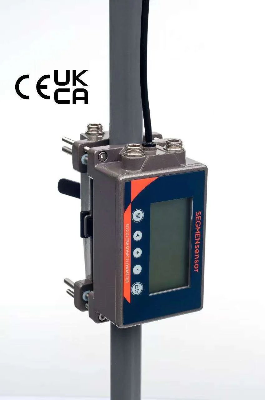
Use a U11 (±0.5%) on UPW distribution loops and chiller mains, a U13 or U12 on PFA and PVDF tool branches and battery test bench lines from DN15, a U10S PRO or U12 on PCW and ESS liquid-cooling mains, and the U11 E version where heat load must be measured. Enter the real tube OD, wall and material and the glycol mix. CMP or electrode slurry, electrolyte, solvent lines in Ex areas, flexible hoses and bores below 12 mm are not suitable.
Where Does a Clamp-On Meter Fit in a Fab, Battery Plant or ESS?
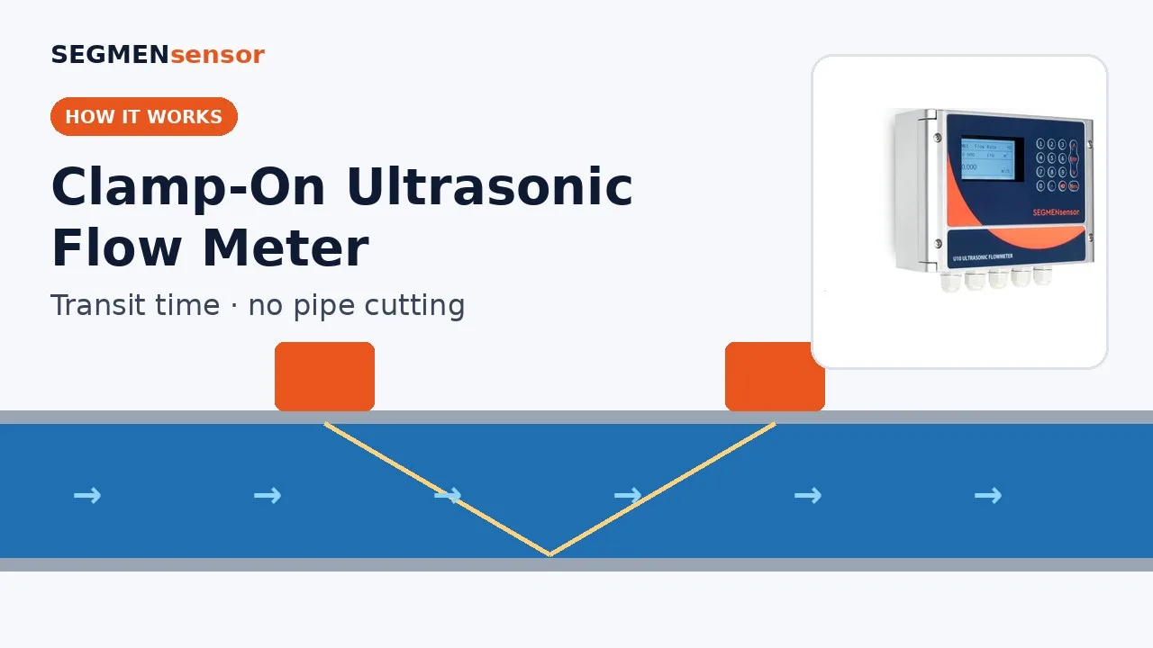
On the clean liquids that serve the process — water systems and cooling loops — rather than on the process chemicals themselves. A clamp-on ultrasonic flow meter sends ultrasonic pulses through the pipe wall with and against the flow; the transit-time difference gives velocity and the inner area of the pipe gives volume flow. The method for liquids in closed conduits is described in ISO 12242 — Measurement of fluid flow in closed conduits: ultrasonic transit-time meters for liquid. Two properties make it a frequent request in these plants: it does not depend on conductivity, so UPW is no harder to measure than tap water, and the transducers sit outside the pipe, so a qualified UPW loop or a filled coolant circuit gets no new fitting, seal or wetted material.
In a fab, the good points are the UPW distribution loop supply and return in the sub-fab, UPW and DI water branches to tools on PFA or PVDF tube from DN15, and tool process cooling water (PCW). Water quality classes for UPW are set out in ASTM D5127 — Standard Guide for Ultra-Pure Water Used in the Electronics and Semiconductor Industries; a clamp-on meter does not touch the water, so it does not affect those values. In battery cell and pack plants, the good points are chiller water to formation, grading and test cabinets and coolant to pack test benches; in an ESS container, the water-glycol main from the liquid-cooling unit to the battery racks. Liquid cooling is one of the battery thermal management approaches compared in NREL's Battery Thermal Management System Design Modeling.
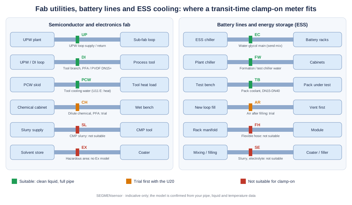
Typical Measuring Points in Fabs, Battery Lines and ESS
The table lists the lines where facility, tool-hook-up and battery-line engineers most often ask for a clamp-on meter. Pipe sizes are typical values for orientation only; model data are from the SEGMENsensor product page and datasheets. We confirm the model from your pipe and liquid data.
| Measuring point | Typical pipe / tube | Medium · temperature | Suggested model | Confirm before ordering |
|---|---|---|---|---|
| UPW distribution loop supply and return (sub-fab) | PVDF or stainless, DN50–DN150 | UPW, near ambient | U11 (±0.5%, from ±0.01 m/s) with A2 sensors; U10S PRO (±1%) for indication | Pipe material and wall (thick PVDF walls: trial with the U20); minimum return velocity in your specification |
| UPW / DI water branch to a process tool | PFA or PVDF tube, DN15–DN40 | UPW or DI water, ambient | U13 (DN15–DN40, PFA and PVDF listed) or U12 (DN15–DN65, PVDF listed) | Measured OD and wall; bore at least 12 mm; where the display can be read in the sub-fab |
| Tool process cooling water (PCW) supply and return | Stainless, PVC or PP, DN25–DN100 | PCW, cooled | U12 on skids up to DN65; U10S PRO above; U11 E version with PT1000 sensors for heat load | Low-flow alarm set point (relay); supply and return pipes for the energy version |
| Fab chilled and cooling water mains | Carbon steel or stainless, DN100–DN600 | Chilled water, cooling water | U11 (15–5000 mm, ±0.5%) | Straight run away from pumps and headers; output to the facility monitoring system |
| ESS liquid-cooling main (unit to battery racks) | Steel or plastic pipe, DN25–DN80 | Water-glycol coolant | U10S PRO or U12; U11 E version where rack heat load is logged | Glycol type and concentration; minimum and maximum coolant temperature; air removed after filling |
| Formation, grading and test cabinet chiller water | PVC, PPR or stainless, DN25–DN100 | Chilled water or water-glycol | U12 (DN15–DN65) per branch; U10S PRO on the header | Pipe material listed for the model; output to the line PLC |
| Battery pack / module test bench coolant | Stainless or plastic tube, DN15–DN40 | Water-glycol, often below 0 °C in cold tests | U13 (−10 to +65 °C, high-temperature option to +105 °C); U10S PRO with A2 sensors (−40 to +80 °C) for colder tests | Lowest test temperature; flow range per test profile |
| Dilute chemical supply to a wet bench | PFA tube, DN15–DN25 | Dilute acid or alkali, may outgas | Trial with the U20 portable meter first; U13 if the signal holds | Bubbles from outgassing (for example peroxide mixes); hazardous-area classification |
Why Do Small PFA and PVDF Tubes Need Extra Care?
Because on a small tube a small data error becomes a large flow error, and plastic tube is specified by outer diameter and wall, not by DN. The meter converts velocity to flow with the inner area you enter. Take a tube of 19.05 mm OD with a 1.6 mm wall: the bore is 15.85 mm. If 1.0 mm were entered as the wall, the meter would calculate a 17.05 mm bore and read about 16% high, because (17.05 / 15.85)² ≈ 1.16 (calculated value). So measure the OD with a caliper, take the wall from the tube specification or an ultrasonic thickness gauge, and select the actual material — PFA, PVDF, PP or stainless — because the speed of sound in the wall differs.
Check the bore against the model range before anything else. The U12 needs an inner diameter of at least 12 mm, so tubes with a smaller bore — most 1/2-inch PFA tubing, for example — are below the range of these meters. The U13 covers DN15–DN40 and lists PFA and PVDF among its pipe materials; the U12 covers DN15–DN65 and lists PVDF, PPR and PPH. Thick-walled PVDF loop pipe attenuates the ultrasonic signal more than steel, so trial it with the U20 before fixing a meter. The U12 and U13 mounting steps are shown in the U12 installation video and the U13 installation video.
Installation Difficulties in Fabs and Battery Plants and How to Handle Them
Congested sub-fab and short straight runs
Tool hook-ups have elbows, valves and filters every few diameters. Keep about 10D of straight pipe upstream and 5D downstream where possible — on a DN25 tube that is only about 250 mm and 125 mm — and stay away from pump outlets and control valves. Use V-mode on small tubes. The full procedure is in the clamp-on flow meter installation guide.
Cleanroom rules for couplant and the transmitter
The transducers need a couplant between sensor face and pipe. Use a couplant your site accepts for that area and keep it under the sensor footprint. On the U10 series and U11, put the transmitter in the sub-fab or a service area: the sensor cable is 9 m as standard and up to 274 m on order, so only the transducers sit on the pipe.
Air in newly filled coolant loops
An ESS or test-bench loop that has just been filled carries air until it has been vented and circulated, and the reading drops out while bubbles pass. Commission the meter after venting, mount at the side of horizontal pipes (3 or 9 o'clock), and avoid high points. The U11 rides through intermittent bubbles or impurities lasting up to 5 seconds; a loop that keeps entraining air needs fixing before it can be measured.
Glycol, low temperature and viscosity
Water-glycol has a different speed of sound and a higher viscosity than water, and both change with temperature. Select or enter the liquid for the actual mix and give us the concentration and the lowest coolant temperature; U12 sensors start at 0 °C, U13 at −10 °C and A2 sensors at −40 °C. Glycol mixes are checked per application before ordering.
Vibration and condensation in ESS containers
Pumps and fans in a container vibrate the pipework, and chilled lines sweat. Mount the transducers away from the pump outlet on a supported pipe section, route cable glands downward, and seal the insulation back over the sensors on chilled lines. Transducers are IP68 and the U10-series transmitter is IP65.
Send your UPW, PCW or coolant line data for a flow meter selection
Tell us the measuring point (UPW loop, tool branch, PCW, chiller water, ESS main, test bench), tube or pipe OD and wall thickness, material (PFA, PVDF, PP, stainless, steel), liquid including glycol type and concentration, temperature range, flow range including low flow, straight run, power, output to the PLC or monitoring system and quantity. OEM volume supply · samples 1–5 pcs in 5–7 working days · production lead time and MOQ confirmed with the quotation · quotation within 24 hours.
How Low a Flow Can You Measure on a Small Tube?
Convert the lowest velocity of the model into flow for your bore. In a 15.85 mm bore, the U12 lower limit of 0.03 m/s is about 0.36 L/min and the U13 lower limit of 0.15 m/s is about 1.8 L/min; the U13 default low-flow cut-off of 0.08 m/s is about 0.95 L/min, below which the display reads zero until the cut-off is changed in the zero settings. For a coolant main, work the other way: a rack loop specified at 30 L/min in a DN25 Schedule 40 pipe (26.6 mm bore) runs at about 0.9 m/s, comfortably inside every model's range (all calculated values from the bores given).
For a permanent check on a tool or rack, use one output as 4-20 mA to the PLC and the relay as a low-flow alarm, or read flow and the totaliser over RS485 Modbus. Where the heat removed from a tool or a battery rack matters, the U11 E version with a PT1000 pair on supply and return measures cooling energy as well as flow. The U20 portable meter checks whether the real flow matches the design before a fixed meter is chosen.
Which Lines Are Not Suitable in Fabs, Battery Plants and ESS?
Slurries, electrolyte, solvent lines in hazardous areas, liquids that outgas or carry air, flexible hoses and tubes below the model range are not suitable for a SEGMENsensor clamp-on meter. Specifically:
- CMP slurry and electrode (cathode or anode) slurry: solids scatter the ultrasonic pulse; the meters measure clean single-phase liquids without solids.
- Electrolyte filling, NMP and solvent lines in hazardous (Ex) areas: SEGMENsensor flow meters have no explosion-protected model.
- Chemical mixes that outgas, and any loop that keeps entraining air for more than a few seconds — trial first with the U20.
- Flexible hoses and quick-coupled hoses to battery racks and modules: the pipe list covers rigid metal and plastic pipe only.
- Tubes with a bore below 12 mm, such as most 1/2-inch PFA tubing, and very small tool lines: below the U12 and U13 range.
- Gases such as nitrogen, CDA and process gases: the meters are for liquids only.
Specifications That Matter for UPW and Coolant Lines
The values below are taken from the SEGMENsensor ultrasonic flow meter product page and datasheets. Compare every model in the U10 to U20 model comparison.
| Parameter | U10S PRO / U11 | U12 | U13 |
|---|---|---|---|
| Pipe size | 15–1200 mm (U10S PRO) · 15–5000 mm (U11) | DN15–DN65, minimum inner diameter 12 mm | DN15–DN40 |
| Pipe materials | Stainless, carbon steel, cast iron, copper, PVC, PP and other rigid plastics | Stainless, carbon steel, copper, PVC, PVDF, PPR, PPH | Stainless, carbon steel, copper, PVC, PVDF, PPR, PPH, PFA |
| Accuracy | ±1% (U10S PRO) · ±0.5% (U11) | ±2% (±1% after calibration) | <3% FS (<1.5% FS after calibration) |
| Flow velocity | ±0.03 to ±5 m/s (U10S PRO) · ±0.01 to ±12 m/s (U11) | 0.03–10 m/s | 0.15–10 m/s; default low-flow cut-off 0.08 m/s |
| Liquid temperature | A2 −40 to +80 °C · H1A to +130 °C · H2A to +180 °C | 0–65 °C · 0–115 °C option | −10 to +65 °C · −10 to +105 °C option |
| Outputs | Choose two: 4-20 mA, pulse (OCT), relay, RS232 / RS485 Modbus; HART optional | Choose two: 4-20 mA, RS485 Modbus, OCT pulse, relay | 4-20 mA and RS485 Modbus; pulse or relay optional |
| Power | 10–36 V DC (90–245 V AC optional on U10S PRO; either on U11) | 10–24 V DC | 20–28 V DC, M12 connector |
| Energy version · certification | Every model available as a heat / cooling (BTU) energy meter with PT1000 sensors · CE, UKCA (no explosion-protected model) | ||
Download the one-page datasheet (PDF)
Pipe size ranges, accuracy, transducer types and temperature ratings, outputs, power supply, enclosure ratings and ordering code for the SEGMENsensor clamp-on ultrasonic flow meter range. No registration required.
How Do You Trial a Line Before Fixing a Meter?
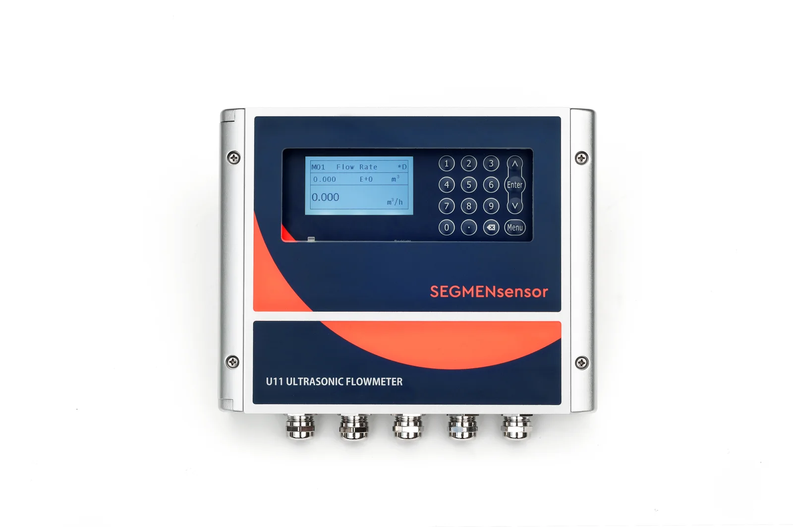
Clamp the U20 portable clamp-on flow meter on the candidate line and log a representative period: a day on a UPW loop including peak draw by the tools, a full test profile on a battery test bench, or a charge and discharge cycle on an ESS loop. Record flow, signal strength and quality on the SD card (logging interval 1–99999 s); the U20 uses F1 or F1H small-pipe sensors on tubes from DN15 to DN40. If the signal holds through the whole period, a fixed meter will work there. The U20 setup is shown in the U20 setup video.
Related Pages
For data center chilled water, CDU loops and BTU metering, read data center cooling water flow monitoring. Purified water and CIP lines are covered in the pharmaceutical and food plant guide and corrosive process liquids in the chemical plant guide. Coolant level in ESS and CDU loops is covered in coolant level sensors for BESS and CDU liquid cooling, and why gassy liquids are a different measuring problem in transit-time vs Doppler ultrasonic flow meters.
What Affects the Quotation?
We do not publish list prices because the configuration drives the quotation: fixed, one-piece or portable, pipe size range and transducer type, accuracy class, energy version, outputs, power supply, cable length and quantity. Quotations are FOB China and exclude international freight and import duties or taxes; payment is 100% T/T in advance, and meters carry a 12-month warranty.
Get a clamp-on flow meter for UPW, fab cooling or battery liquid cooling
U11 for UPW loops and chilled water mains, U12 and U13 for PFA, PVDF and small coolant lines, U10S PRO for PCW and ESS mains, U11 E version for heat load, U20 for trials. OEM volume supply · samples 1–5 pcs in 5–7 working days · production lead time and MOQ confirmed with the quotation · quotation within 24 hours. Download the clamp-on flow meter datasheet (PDF).
Frequently Asked Questions
Yes. Transit-time measurement does not depend on conductivity, so UPW and DI water in a full pipe are measured from outside the pipe with nothing added to the loop. Enter the real pipe OD, wall and material, and trial thick PVDF walls with the U20 first.
The U13 (DN15–DN40) lists PFA and PVDF among its pipe materials and the U12 (DN15–DN65, minimum inner diameter 12 mm) lists PVDF. Tubes with a bore below 12 mm, such as most 1/2-inch PFA tubing, are below that range.
Usually, if the loop is full and free of air. Glycol changes the speed of sound and the viscosity, so send the glycol type, concentration and temperature range; the meter is set up for that liquid and the application is checked before ordering.
It depends on the bore. In a 15.85 mm bore the U12 starts at 0.03 m/s (about 0.36 L/min) and the U13 at 0.15 m/s (about 1.8 L/min); the U13 default low-flow cut-off of 0.08 m/s is about 0.95 L/min (calculated values).
No. SEGMENsensor clamp-on meters measure clean single-phase liquids without solids. CMP slurry, cathode or anode slurry, electrolyte filling lines and solvent lines in hazardous areas need another flow measurement principle.
Samples of 1–5 pcs ship in 5–7 working days. Production lead time and MOQ are confirmed with the quotation, which we send within 24 hours on working days, FOB China.