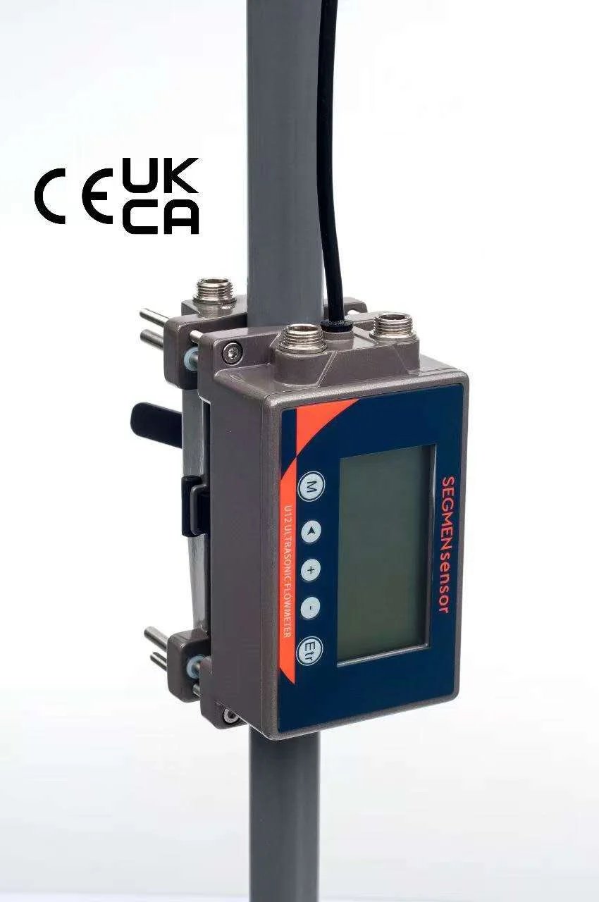
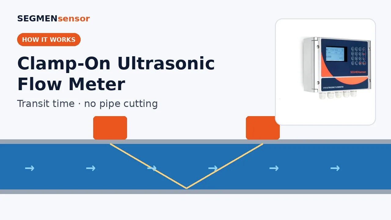
Use a U10S PRO with B1 or B1H small-pipe sensors (from 15 mm) on purified water generation and loop lines, a U11 (±0.5%, from ±0.01 m/s) where loop return velocity or CIP flow must be verified, H1A sensors (to +130 °C) on hot-sanitised loops and hot CIP supply, and U12 or U13 one-piece meters for indication on tubes up to DN65. Enter the real tube OD and wall. CIP return, steam and SIP, carbonated, pulpy or viscous product and flexible hoses are not suitable.
Where Does a Clamp-On Meter Fit in a Pharmaceutical or Food Plant?
On the clean, full-pipe liquids that serve the process — water systems, CIP supply and utilities — rather than on gassy, pulpy or viscous product. A clamp-on ultrasonic flow meter sends ultrasonic pulses through the tube wall with and against the flow; the transit-time difference gives velocity and the tube's inner area gives volume flow. The method for liquids in closed conduits is described in ISO 12242 — Measurement of fluid flow in closed conduits: ultrasonic transit-time meters for liquid. The reason hygienic plants ask for it is simple: the transducers sit outside the tube, so an existing, passivated 316L line gets no new tee, weld, gasket or instrument port, and no new dead leg.
In a pharmaceutical water system the good points are the purified water (PW) leaving the RO / EDI unit, the distribution loop supply and return — including loops that run hot for self-sanitisation — and the CIP supply to tanks and lines. CIP return is a trial point because it often carries air and runs part-full. Clean steam and SIP are not liquids. In a food or beverage plant, the incoming water main, softened water, chilled and cooling water to tank jackets, and hot water for pasteurisers, bottle washers and blanchers are good points; clear, still product needs a trial; carbonated product after the carbonator, pulpy or viscous product and flexible hoses are not suitable.
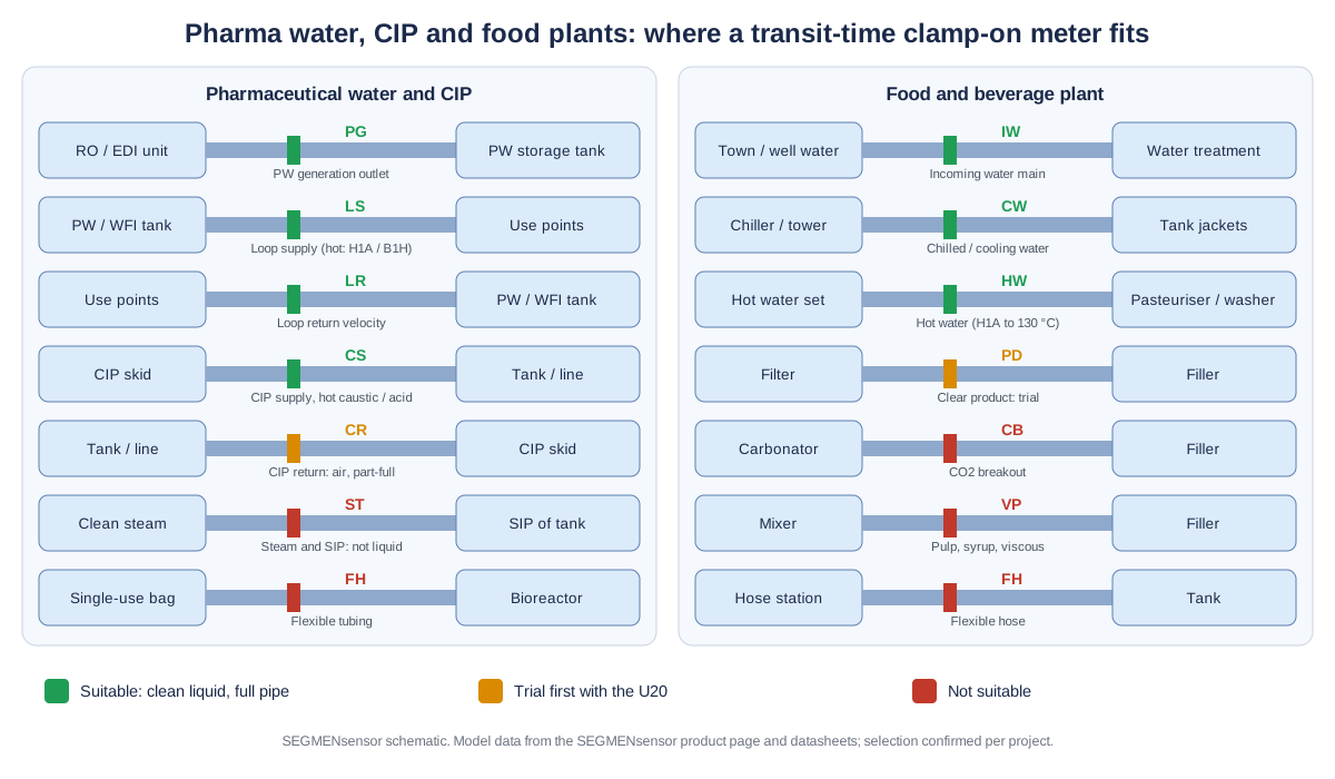
Typical Measuring Points in Pharmaceutical and Food Plants
The table lists the lines where water-system, utilities and CIP engineers most often ask for a clamp-on meter. Tube sizes are typical values for orientation only; model data are from the SEGMENsensor product page and datasheets. We confirm the model from your tube and liquid data.
| Measuring point | Typical tube / pipe | Medium · temperature | Suggested model | Confirm before ordering |
|---|---|---|---|---|
| PW generation outlet (RO / EDI product to storage tank) | 316L sanitary tube, 1"–2" (25.4–50.8 mm OD) | Purified water, ambient | U10S PRO with B1 sensors (DN15–DN40, 0–65 °C) or A2; U13 (DN15–DN40) for indication | Measured OD and wall; flow during start-up dump-to-drain; output to the water system PLC |
| PW / WFI distribution loop supply | 316L sanitary tube, 1½"–3" | Ambient, or hot loop for self-sanitisation | U10S PRO or U11; B1H (0–115 °C) on tubes to DN40, H1A (to +130 °C) above | Maximum sanitisation temperature; whether the reading is for monitoring or GMP-critical (QA decision) |
| Loop return (velocity monitoring before the tank) | 316L sanitary tube, 1"–2½" | As loop supply, lowest flow of the loop | U11 (±0.5%, from ±0.01 m/s); relay output for a low-flow alarm | Minimum return velocity in your URS; straight run after the last use point |
| CIP supply to tanks and lines | 316L sanitary tube, 1½"–3" | Rinse water, hot detergent, acid | U10S PRO or U11 with H1A or B1H sensors | Maximum CIP temperature; whether SIP follows on the same tube; signal through a full cycle |
| CIP return | 316L sanitary tube, 1½"–3" | Return liquid with air, often part-full | Trial with the U20 portable meter first, on the return pump discharge | Full pipe at the measuring point during every CIP step |
| Chilled and cooling water to jackets and heat exchangers | Stainless or carbon steel, DN50–DN200 | Chilled water, cooling water | U10S PRO (±1%); U11 E version with PT1000 sensors for cooling energy | Supply and return pipes for the energy version; insulation opening at the sensors |
| Incoming water main / softened water (food and beverage) | Stainless, carbon steel or PVC, DN80–DN300 | Town or well water, softened water, ambient | U11 (15–5000 mm, ±0.5%) | Straight run away from pumps and tees; output to the BMS or energy system |
| Hot water to pasteurisers, bottle washers and blanchers | Stainless, insulated, DN25–DN100 | Hot water, often above +80 °C | U10S PRO or U11 with H1A (to +130 °C) or H2A (to +180 °C) | Maximum water temperature; no flashing at the measuring point |
Why Do Sanitary Tube Dimensions Matter So Much?
Because the meter turns velocity into flow using the inner area you enter, and sanitary tube is not sized like process pipe. Hygienic tubing is specified by outer diameter with a thin wall: a 1-inch tube is 25.4 mm OD with a 1.65 mm wall, so the bore is 22.1 mm; a 2-inch tube is 50.8 mm OD, 47.5 mm bore. If DN25 Schedule 10S pipe data (27.9 mm bore) were entered for that 1-inch tube, the meter would read about 59% high, because the area ratio is (27.9 / 22.1)² ≈ 1.59 (calculated value).
So measure, do not assume: take the OD with a circumference tape or caliper, read the wall from the tube certificate or an ultrasonic thickness gauge, and enter stainless steel as the material. On tubes up to DN40, the U10S PRO and U11 use B1 or B1H small-pipe sensors; the U12 takes tubes from DN15 to DN65 with a minimum inner diameter of 12 mm, and the U13 covers DN15–DN40. The U12 and U13 mounting steps are shown in the U12 installation video and the U13 installation video.
Installation Difficulties in Hygienic Plants and How to Handle Them
Hot loops, hot CIP and SIP temperatures
Hot-sanitised water systems commonly run at 65–80 °C — the FDA's Guide to Inspections of High Purity Water Systems notes that hot systems in that range are recognised as self-sanitising. That is at or above the +80 °C limit of standard A2 sensors, so choose H1A (to +130 °C) on larger tubes or B1H (0–115 °C) on tubes up to DN40. If the same tube is steamed in place, check the SIP temperature against the sensor rating: H1A or H2A (to +180 °C) can stay on, while B1, B1H, U12 and U13 sensors should be removed before steaming above their rating. No meter reads during SIP — steam is not a liquid.
Thin, polished tube and short runs between fittings
Skids and loops are compact, with elbows, tees and valves every few diameters. Keep about 10D of straight tube upstream and 5D downstream where possible — on a 1½-inch tube that is only about 350 mm and 175 mm — and avoid the outlet of a pump or a diaphragm valve. Use the mounting rails or clamps supplied, tighten evenly on thin wall, and choose V-mode on small tubes. The full procedure is in the clamp-on flow meter installation guide.
Couplant and transmitter position in clean areas
The transducers need a couplant between sensor face and tube. Use a couplant your site accepts for that room class and keep it under the sensor footprint. Put the transmitter in the technical area or service corridor rather than the cleanroom: the sensor cable is 9 m as standard and up to 274 m on order on the U10 series and U11, so only the transducers sit on the tube.
Air in CIP return and after tank spray balls
CIP return lines carry air from spray devices and often run part-full between pulses of the return pump. Measure on the return pump discharge, mount at the side of horizontal tubes (3 or 9 o'clock), and log a full CIP cycle with the U20 before committing to a fixed meter. The U11 rides through intermittent bubbles or impurities lasting up to 5 seconds; a line that drains or aerates for longer is not a clamp-on point.
Washdown, condensation and humidity
Transducers are IP68 and the U10-series transmitter is IP65 (enclosure codes per IEC 60529 — Degrees of protection provided by enclosures (IP Code)). Keep the transmitter out of direct washdown spray, route cable glands downward, and on chilled-water lines seal the insulation back over the sensors so condensate does not collect under them.
Send your water system or CIP line data for a flow meter selection
Tell us the measuring point (PW generation, loop supply or return, CIP supply or return, cooling water, hot water), tube OD and wall thickness, material, liquid and temperature range including sanitisation and SIP, flow range including low flow, straight run, power, output to the PLC or BMS and quantity. OEM volume supply · samples 1–5 pcs in 5–7 working days · production lead time and MOQ confirmed with the quotation · quotation within 24 hours.
How Do You Check CIP Supply Flow and Loop Return Velocity?
Convert the velocity your specification asks for into flow for the real tube bore, then read the meter against it. For example, if a CIP specification sets 1.5 m/s in a 2-inch tube (47.5 mm bore), the supply must deliver about 9.6 m³/h; the same velocity in a 1-inch tube (22.1 mm bore) is about 2.1 m³/h. A loop return of 1.0 m/s in a 1½-inch tube (34.8 mm bore) is about 3.4 m³/h (all calculated values from the bores given). The meter can display velocity directly, which avoids the conversion on site.
For a permanent check, fix a U11 on the loop return and use one output as 4-20 mA to the water system PLC and the relay as a low-flow alarm; the U11 measures from ±0.01 m/s, the U10 series from ±0.03 m/s. For CIP, a fixed meter on the supply gives flow per step and the totaliser gives volume per cycle; read it over RS485 Modbus or count the pulse output in the CIP controller. Whether these readings become part of a validated, GMP-critical record — and what calibration and data-integrity controls apply — is decided by your quality unit, not by the meter.
Which Lines Are Not Suitable in Pharma and Food Plants?
CIP return that is part-full or aerated, steam and SIP, carbonated or gassy product, pulpy or viscous product, flexible or single-use tubing and hazardous areas are not suitable for a SEGMENsensor clamp-on meter. Specifically:
- Clean steam, SIP and condensate that flashes: SEGMENsensor clamp-on meters are for single-phase liquids only.
- CIP return that runs part-full or carries air for more than a few seconds — trial first, and measure supply instead if it fails.
- Carbonated beverages after the carbonator and any line where CO2 or air breaks out: bubbles scatter the ultrasonic pulse.
- Product with pulp, fruit pieces or particles, and high-viscosity product such as syrups, sauces or chocolate: send the product data if in doubt, but plan for another flow measurement principle.
- Flexible hoses, silicone tubing and single-use bioprocess assemblies: the pipe list covers rigid metal and plastic pipe only.
- Measurements that need a hygienic certification on the instrument (for example a 3-A or EHEDG requirement in your specification): SEGMENsensor flow meters carry CE and UKCA marking and hold no hygienic-design certification.
- Hazardous (Ex) areas, such as solvent or ethanol handling in API plants and some extraction areas: SEGMENsensor flow meters have no explosion-protected model.
Specifications That Matter for Purified Water and CIP Lines
The values below are taken from the SEGMENsensor ultrasonic flow meter product page and datasheets. Compare every model in the U10 to U20 model comparison.
| Parameter | U10S PRO / U11 | U12 | U13 |
|---|---|---|---|
| Pipe size | 15–1200 mm (U10S PRO) · 15–5000 mm (U11) | DN15–DN65, minimum inner diameter 12 mm | DN15–DN40 |
| Accuracy | ±1% (U10S PRO) · ±0.5% (U11) | ±2% (±1% after calibration) | <3% FS (<1.5% FS after calibration) |
| Flow velocity | ±0.03 to ±5 m/s (U10S PRO) · ±0.01 to ±12 m/s (U11) | 0.03–10 m/s | 0.15–10 m/s |
| Sensor temperature | B1 0–65 °C, B1H 0–115 °C (DN15–DN40) · A2 −40 to +80 °C · H1A to +130 °C · H2A to +180 °C | B1 0–65 °C · B1H 0–115 °C | B1 −10 to +65 °C · B1H −10 to +105 °C |
| Outputs | Choose two: 4-20 mA, pulse (OCT), relay, RS232 / RS485 Modbus; HART optional | Choose two: 4-20 mA, RS485 Modbus, OCT pulse, relay | 4-20 mA and RS485 Modbus; pulse or relay optional |
| Power | 10–36 V DC (90–245 V AC optional on U10S PRO; either on U11) | 10–24 V DC | 20–28 V DC, M12 connector |
| Energy version · certification | Every model available as a heat / cooling (BTU) energy meter with PT1000 sensors · CE, UKCA (no hygienic-design certification, no explosion-protected model) | ||
Download the one-page datasheet (PDF)
Pipe size ranges, accuracy, transducer types and temperature ratings, outputs, power supply, enclosure ratings and ordering code for the SEGMENsensor clamp-on ultrasonic flow meter range. No registration required.
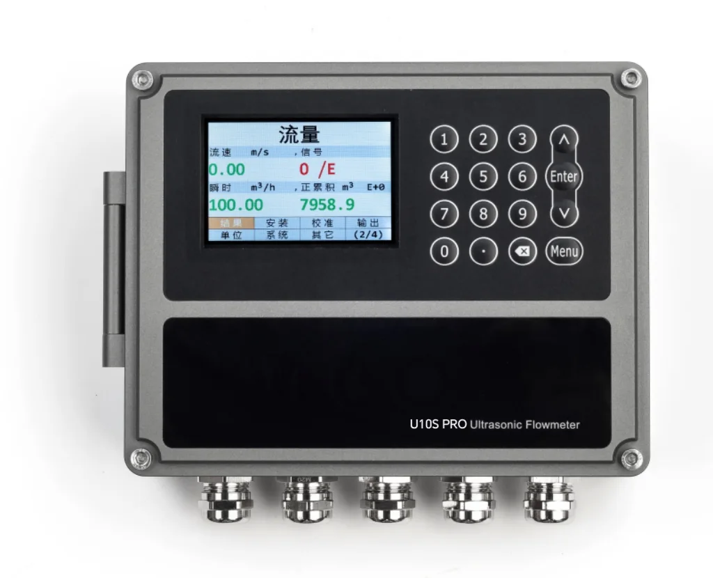
How Do You Trial a Line Before Fixing a Meter?
Clamp the U20 portable clamp-on flow meter on the candidate line and log a complete cycle: a full CIP programme with every rinse, detergent and acid step, or a day on a water loop including peak draw-off and sanitisation. Record flow, signal strength and quality on the SD card (logging interval 1–99999 s); the U20 uses F1 or F1H small-pipe sensors on tubes from DN15 to DN40 and P2H sensors to +130 °C on hot lines. If the signal holds through the whole cycle, a fixed U10S PRO or U11 will work there. The U20 setup is shown in the U20 setup video.
Related Pages
For clean water pipes in general, read the ultrasonic flow meter for water selection guide. Corrosive process liquids are covered in the chemical plant guide, process water in paper mills and dyehouses, and chilled water and BTU metering in data center cooling water flow monitoring. Why gassy and particle-laden liquids are a different measuring problem is explained in transit-time vs Doppler ultrasonic flow meters.
What Affects the Quotation?
We do not publish list prices because the configuration drives the quotation: fixed, one-piece or portable, tube size range and transducer type (small-pipe, standard or high-temperature), accuracy class, outputs, power supply, cable length and quantity. Quotations are FOB China and exclude international freight and import duties or taxes; payment is 100% T/T in advance, and meters carry a 12-month warranty.
Get a clamp-on flow meter for purified water, CIP or plant utilities
U10S PRO and U11 with B1H or H1A sensors for water loops and CIP supply, U12 and U13 for small tubes, U11 for incoming water mains and cooling energy, U20 for trials. OEM volume supply · samples 1–5 pcs in 5–7 working days · production lead time and MOQ confirmed with the quotation · quotation within 24 hours. Download the clamp-on flow meter datasheet (PDF).
Frequently Asked Questions
Yes. Purified water in a full, recirculating 316L loop is a clean single-phase liquid, so a transit-time clamp-on meter measures it from outside the tube without adding a port or dead leg. Use B1H or H1A sensors if the loop is hot-sanitised.
SEGMENsensor clamp-on meters carry CE and UKCA marking and hold no hygienic-design certification. Nothing enters the line, but whether that is acceptable for a given measurement, and whether it is GMP-critical, is decided by your QA.
Only after a trial. CIP return often carries air from spray devices and runs part-full. Log a full CIP cycle with the U20 on the return pump discharge; if the signal drops out, measure the CIP supply instead.
Standard A2 sensors cover −40 to +80 °C. For hot loops and hot CIP choose H1A (to +130 °C) on larger tubes or B1H (0–115 °C) on tubes up to DN40; remove B1, B1H, U12 and U13 sensors before SIP above their rating.
The measured outer diameter and wall thickness, not a nominal DN. A 1-inch sanitary tube is 25.4 mm OD with a 1.65 mm wall (22.1 mm bore); entering DN25 Schedule 10S pipe data instead would make the meter read about 59% high.
Samples of 1–5 pcs ship in 5–7 working days. Production lead time and MOQ are confirmed with the quotation, which we send within 24 hours on working days, FOB China.