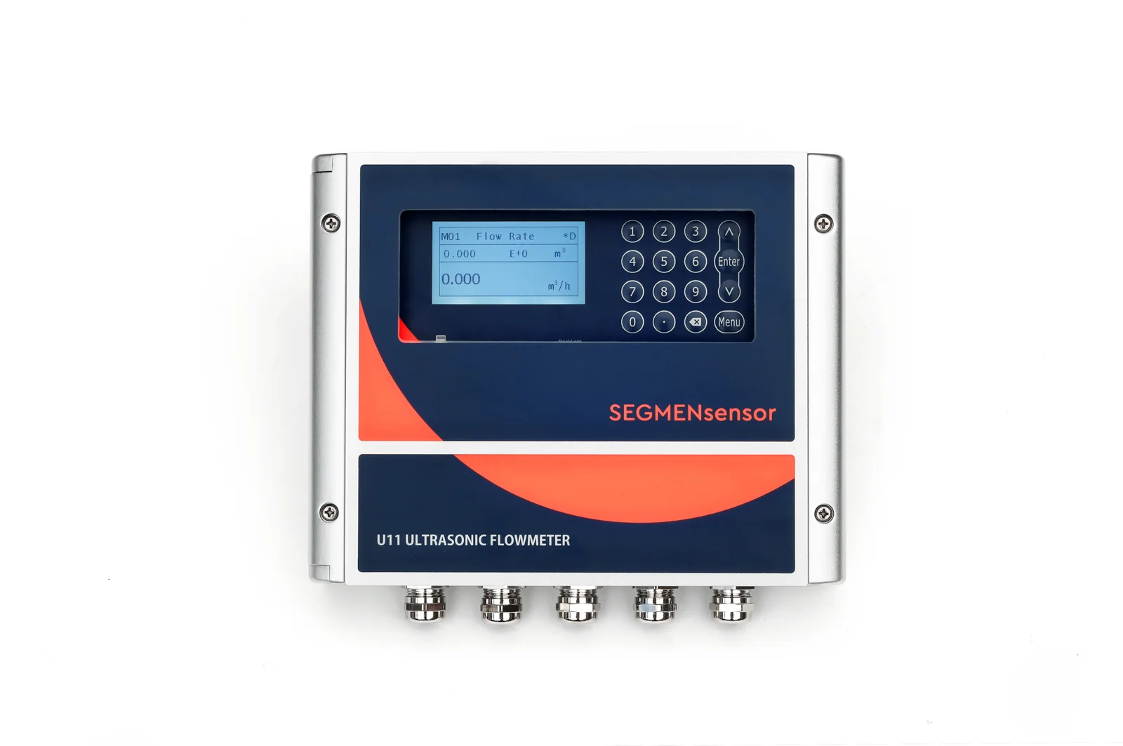
To monitor chilled-water or cooling-water flow in a data center, fit one clamp-on ultrasonic flow meter per pipe on a straight, full section (typically 10D upstream and 5D downstream), remove the insulation only at the transducer spot, and connect each transmitter to the BMS or DCIM over RS485 Modbus RTU with its own slave address, or over 4–20 mA. The pipe is never cut, so the cooling loop keeps running during installation.
Why use clamp-on flow meters on data center cooling water?
Clamp-on meters are used on data center cooling water because they can be added to a live loop: the transducers sit on the outside of the pipe, so there is no shutdown, no new flange or joint that could leak, and no pressure drop in the loop. For an operating facility this matters more than for a new build, because draining a chilled-water or cooling-water loop to fit an inline meter means planning around cooling redundancy.
- No shutdown: the two transducers are strapped to the pipe while water keeps flowing; only the insulation is opened locally at the measuring point.
- No new leak point: nothing penetrates the pipe wall, so there is no gasket, weld or threaded connection added near IT equipment.
- No pressure drop: the flow path is unchanged, so pump duty and loop balancing are not affected by the meter.
- Bidirectional: the U11 measures ±0.01 to ±12 m/s in both directions, useful on bypass or crossover lines where flow can reverse.
The measuring principle is the transit-time method described in ISO 12242 — ultrasonic transit-time meters for liquid: the meter compares the travel time of ultrasonic pulses sent with and against the flow, and the difference is proportional to the flow velocity. It needs a clean liquid in a full pipe, which is the normal state of a closed chilled-water or cooling-water loop. If you are unsure whether transit-time fits your liquid, see transit-time vs Doppler ultrasonic flow meters.
Example: four cooling-water pipes reported to the monitoring room
A recent order from a data center in North China shows the typical request. The site needed flow readings from four cooling-water pipes in the monitoring room, and the proposal was first reviewed by the site's HVAC engineer before ordering. The table shows how each requirement was answered.
| Requirement from the site | SEGMENsensor solution |
|---|---|
| Measure flow on 4 cooling-water pipes | 4 sets of U11, each one transmitter plus one pair of clamp-on transducers (one set per pipe) |
| Send flow data to the monitoring room | RS485 Modbus output on every transmitter, each meter with its own slave address; 4–20 mA offered as the alternative output |
| Install on a running cooling system | Clamp-on transducers on the outside of the pipe: no cutting, no shutdown, no added leak point |
| Cooling-water temperature | Standard A2 transducers, IP68, −40 to +80 °C |
| Technical sign-off by the HVAC engineer | Pipe data, output type and installation points reviewed with the engineer before the order |
Which U11 configuration fits a data center water loop?
For most chilled-water and cooling-water pipes the standard configuration is a U11 wall-mount transmitter with A2 clamp-on transducers and an RS485 Modbus output. The table lists the U11 options from the datasheet and what each one means on a data center loop.
| Parameter | U11 specification | What it means for a data center |
|---|---|---|
| Measuring principle | Transit-time clamp-on; FPGA-based signal processing with the TGA timing algorithm | No wetted parts; the loop is not opened |
| Accuracy / repeatability | ±0.5% / 0.1% | Suitable for trending, loop balancing and energy calculations |
| Velocity range | ±0.01 to ±12 m/s, bidirectional | Covers low flow and reversing flow, e.g. on bypass lines |
| Pipe size | 15–5000 mm, depending on transducer | From small branch lines to main headers |
| A2 clamp-on transducers (standard) | IP68, −40 to +80 °C | Chilled water and cooling water |
| B1 / B1H transducers | DN15–DN40 | Small branch pipes |
| H1A / H2A transducers | Up to +130 °C / up to +180 °C | Hot-water or heat-recovery loops |
| Outputs | Choose two of 4–20 mA, OCT pulse, relay, RS232 Modbus, RS485 Modbus; HART optional | RS485 Modbus to the BMS/DCIM, or 4–20 mA to analog inputs |
| Power supply | 90–245 VAC or 10–36 VDC | Mains or a DC panel supply |
| Data logging | Fcard, expandable to 32 GB | Local record if the network link is interrupted |
| Transducer cable | 9 m standard, custom up to 274 m | The transmitter can be mounted away from the pipe, e.g. on a wall or panel |
| Measuring points | One transmitter + one transducer pair = one pipe | 4 pipes = 4 sets |
| Certification | CE, UKCA; no explosion-proof version | For non-hazardous plant rooms |
Download the U11 datasheet (PDF, English, 3 pages) Specifications, ordering code, sensor options, BTU wiring and installation rules for your HVAC engineer's review. Chinese original also available.
To compare the U11 with the other SEGMENsensor clamp-on models, see the U10 to U20 clamp-on flow meter model comparison.
How do I get flow data to the control room, BMS or DCIM?
Use the RS485 Modbus output: each U11 becomes a Modbus RTU slave that the BMS, DCIM gateway or monitoring-room controller polls for flow rate and totals. This is standard Modbus RTU practice, so no special driver is needed.
- Give each meter a different slave address. With four pipes, set four different addresses so the master can read every meter on the same bus.
- Use shielded twisted-pair cable for the RS485 bus and keep it away from power cables and variable-frequency drives.
- Match the communication settings (baud rate and data format) on the meters and the master.
- Map the registers in the BMS. The U11 register map is supplied with the documentation on request; send us your BMS or DCIM point list and we confirm the registers for flow rate, totals and status.
If the controller only has analog inputs, order the 4–20 mA output instead; because each U11 offers two outputs, one transmitter can provide both RS485 Modbus and 4–20 mA, or Modbus plus an OCT pulse for a separate totaliser. The Fcard data logger (expandable to 32 GB) keeps a local record at the meter. More background on Modbus wiring is in the RS485 Modbus RTU sensors guide.
Chilled water BTU and cooling energy metering
For cooling energy (BTU) metering, use the U11 E type: it is an ultrasonic cooling/heating energy meter that adds a pair of PT1000 temperature sensors on the supply and return pipes and calculates energy from the measured flow and the supply/return temperature difference (ΔT).
On chilled water the ΔT between supply and return is often small. Energy is the product of flow and ΔT, so a small temperature error becomes a large share of a small ΔT: the accuracy of the energy value depends on both the flow measurement and the temperature measurement. Install both PT1000 sensors with the same care as the flow transducers and tell us your design supply and return temperatures when you request the E type. For energy-efficiency design context on data center cooling, see the US DOE FEMP Best Practices Guide for Energy-Efficient Data Center Design (PDF).
Where should the transducers go on a chilled-water pipe?
Put the transducers on a straight, always-full section, typically with 10D of straight pipe upstream and 5D downstream, away from pump outlets, valves and elbows. The full procedure is in how to install a clamp-on ultrasonic flow meter; the points specific to chilled and cooling water are:
- Full pipe and clean liquid: avoid high points where air collects.
- Side position on horizontal pipes: mount at the side of the pipe, not on the top (air) or bottom (sediment).
- Avoid disturbances: keep away from pump outlets, valves and elbows; respect the typical 10D upstream / 5D downstream straight run.
- Insulation: remove the insulation locally at the transducer spot only, so the transducers sit on the bare pipe surface, then close the insulation around them.
- Signal check: commission only when the signal strength is 60% or more.
What data does the HVAC engineer need to send?
Send the items below for each pipe; with them we can confirm the transducer type, output and number of sets before you request qualification samples.
| Item | Why it is needed |
|---|---|
| Number of pipes / measuring points | One U11 set per pipe |
| Pipe outer diameter and wall thickness | Sets the transducer spacing and selects A2 or B1/B1H transducers |
| Pipe material and any liner | Affects the ultrasonic path and signal strength |
| Liquid and temperature range | Confirms A2 (−40 to +80 °C) or H1A/H2A transducers |
| Insulation type at the measuring point | Plans local removal at the transducer spot |
| Available straight run and nearby pumps, valves and elbows | Checks the typical 10D / 5D requirement |
| Output to the control room (RS485 Modbus, 4–20 mA, pulse, relay, HART) | Selects the two outputs per transmitter |
| BMS / DCIM point list and Modbus addresses | Prepares the register mapping |
| Power available (AC or DC) | 90–245 VAC or 10–36 VDC version |
| Distance from pipe to transmitter location | Transducer cable: 9 m standard, custom up to 274 m |
| Energy metering needed? Supply and return pipes | Decides whether the U11 E type with PT1000 sensors is required |
| Project quantity or annual volume | Plans samples and production |
Supply terms for OEM and project buyers
| Term | SEGMENsensor |
|---|---|
| Supply model | OEM volume supply; production planned around project or annual volume |
| Qualification samples | 1–5 pcs in 5–7 working days |
| Production lead time | 3–5 weeks |
| Warranty | 12 months |
| Delivery term | FOB China |
| Response | Reply within 24 hours |
Send your pipe list for an engineering review
Pipe sizes, material, liquid temperature, straight run, BMS output and quantity. We confirm the U11 configuration and can ship 1–5 qualification samples in 5–7 working days. The clamp-on flow meter datasheet (PDF) lists the ordering code.
Standards and references
- ISO 12242 — Measurement of fluid flow in closed conduits: ultrasonic transit-time meters for liquid
- US DOE Federal Energy Management Program (FEMP): Best Practices Guide for Energy-Efficient Data Center Design (PDF)
Related reading: CDU liquid-cooling sensor guide · ultrasonic flow meters for water · SEGMENsensor clamp-on ultrasonic flow meter range · flow meter manuals and documents
Frequently Asked Questions
Yes. Chilled water and cooling water in a data center are clean liquids in full pipes, which is the condition a transit-time clamp-on meter needs. On the SEGMENsensor U11 the standard A2 clamp-on transducers are IP68 and rated −40 to +80 °C, so they suit chilled and cooling water; the meter is specified at ±0.5% accuracy and 0.1% repeatability.
Order the U11 with an RS485 Modbus output and wire it to the Modbus RTU master in the BMS, DCIM or monitoring-room controller, giving each meter a different slave address on one shielded twisted-pair RS485 bus. If the controller only accepts analog inputs, use the 4–20 mA output instead. The register map is supplied with the documentation on request.
Four sets. One U11 transmitter with one pair of clamp-on transducers measures one pipe, so four pipes need four transmitters and four transducer pairs. On an RS485 bus each of the four meters gets its own Modbus slave address.
Yes, as the U11 E type. It adds a pair of PT1000 temperature sensors on the supply and return pipes and calculates cooling or heating energy from the flow and the supply/return temperature difference. Because chilled-water temperature differences are often small, the energy accuracy depends on both the flow measurement and the temperature measurement.
No. The transducers clamp to the outside of the pipe, so the loop keeps running, no new joint or leak point is added and there is no pressure drop. Remove the insulation locally at the transducer spot, keep typically 10D of straight pipe upstream and 5D downstream away from pump outlets, valves and elbows, and confirm a signal strength of 60% or more.
The U11 covers pipe sizes from 15 to 5000 mm depending on the transducer. Standard A2 clamp-on transducers are IP68 and rated −40 to +80 °C, B1/B1H transducers cover DN15–DN40, H1A transducers reach +130 °C and H2A transducers +180 °C. The transmitter runs on 90–245 VAC or 10–36 VDC and carries CE and UKCA marking; there is no explosion-proof version.