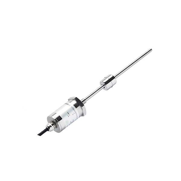
A CDU cooling system requires three sensor types: a coolant level sensor (magnetostrictive or float-type) in the expansion reservoir, a clamp-on ultrasonic flow meter on the primary loop, and pressure transmitters at the pump inlet and outlet. Together, these enable leak detection, flow verification, and differential pressure monitoring for 24/7 AI data center operations.
Why CDU Sensor Monitoring Is Critical for AI Data Centers
The push toward higher-density AI compute has fundamentally changed data center thermal management. NVIDIA's GB200 NVL72 rack delivers up to 600 kW of compute per rack — a thermal load that air cooling cannot handle. Direct liquid cooling (DLC) through Coolant Distribution Units (CDUs) is now the standard for AI server deployments at scale, including HGX B200 clusters and high-performance GPU farms.
A CDU circulates chilled water or engineered coolant (typically deionized water with corrosion inhibitors, or a propylene glycol mixture) from a facility chiller to cold plates mounted directly on processor packages. The fluid absorbs heat and returns to the CDU heat exchanger to reject thermal energy back to the facility cooling loop.
Unlike traditional CRAC-based air cooling, where a fan failure is gradual and recoverable, a CDU coolant loss can destroy a $500,000 GPU cluster within minutes. Accurate, continuous sensor monitoring is therefore not optional — it is a safety system. Three failure modes drive the instrumentation requirement:
- Coolant loss: A fitting failure or micro-leak that empties the expansion reservoir. Caught by coolant level sensors triggering a low-level alarm and automatic pump shutdown.
- Flow blockage: A fouled filter or closed valve that reduces coolant flow below the server's minimum. Caught by the ultrasonic flow meter dropping below the setpoint.
- Pump failure: Loss of differential pressure across the pump. Caught by pressure transmitters at pump inlet and outlet showing collapsed differential.
The following sections cover sensor selection for each measurement point in detail — starting with the most overlooked: coolant level monitoring.
Coolant Level Sensor for CDU Expansion Reservoirs
The expansion reservoir (also called the buffer tank or surge tank) in a CDU serves two functions: it accommodates thermal expansion of the coolant as temperature rises, and it acts as the primary visual indicator of coolant system integrity. If the level in the reservoir drops, coolant has left the loop — either through a leak, evaporation, or improper fill after maintenance.
Recommended Sensor Type: Magnetostrictive Level Sensor
For continuous level monitoring in CDU expansion reservoirs, magnetostrictive level sensors are the engineering-preferred solution. The measurement principle operates without any wetted electronics: a permanent magnet float on the fluid surface and an external waveguide produce a torsional ultrasonic pulse whose travel time is measured to determine float position to ±0.05 mm resolution.
This matters in CDU applications for two reasons. First, high-purity deionized water or engineered coolants must not be contaminated by sensor corrosion or component shedding — a magnetostrictive sensor has only a stainless steel float and guide rod inside the fluid. Second, AI data center CDUs operate 24/7/365 with essentially zero tolerance for unplanned downtime; the non-contact measurement principle eliminates mechanical wear and sensor drift over time.
Output options for DCIM integration include 4–20 mA analog (universal), Modbus RTU / RS-485, and SSI / CANopen for industrial bus integration. No electronics are buried inside the fluid path — the signal conditioning electronics are sealed in a detachable head that can be removed and replaced without draining the tank.
For compact CDU enclosures, SEGMENsensor manufactures custom stroke lengths starting at 25 mm. Standard connection threads are G1/2", G3/4", and G1", with flanged versions (DN25–DN50) for higher-pressure reservoirs. See our magnetostrictive sensor product page for full specifications.
Alternative: Float-Type Liquid Level Switch
Where only alarm switching is needed (not continuous measurement), a magnetic float liquid level sensor provides a lower-cost solution. A reed switch inside the stainless steel guide tube is actuated when the float magnet passes the switch point. Multiple switch points can be built into a single sensor body for high-level and low-level alarms simultaneously. Float switches are compact, inherently failsafe, and available in 316L stainless steel, PVDF, or PTFE for coolant compatibility.
Coolant Level Sensor Comparison: Which Technology for CDU?
No single level sensing technology is optimal for every CDU configuration. The table below compares the four viable options across the parameters that matter most in data center liquid cooling applications.
| Technology | Measurement Type | Resolution | Wetted Electronics | Coolant Compatibility | DCIM Output | Typical Cost |
|---|---|---|---|---|---|---|
| Magnetostrictive Recommended | Continuous | 0.001–0.05 mm | ✓ None | DI water, glycol, all coolants | 4–20 mA, Modbus, SSI | $$ |
| Magnetic Float Switch | Point (switch) | N/A | ✓ None | DI water, glycol, oil | NPN/PNP relay | $ |
| Capacitive | Continuous or point | 1–5 mm | ✗ Electrode wetted | Varies; may drift with coolant chemistry changes | 4–20 mA | $ |
| Ultrasonic (non-contact) | Continuous | 1–3 mm | ✓ None | All liquids | 4–20 mA, Modbus | $$ |
For most CDU expansion tanks, the magnetostrictive sensor is the correct choice: it delivers the continuous high-resolution measurement needed for leak trending, has no wetted electronics to contaminate high-purity coolant, and provides the analog or digital output required by DCIM platforms.
CDU Coolant Flow Monitoring with Clamp-On Ultrasonic Flow Meters
Flow rate monitoring on the primary coolant loop serves two purposes: it verifies that sufficient coolant volume is reaching the server cold plates, and it provides the flow signal needed to calculate actual heat transfer when combined with supply and return temperature sensors.
The engineering-preferred solution for CDU coolant loop flow measurement is a clamp-on ultrasonic flow meter. Unlike insertion or inline meters, clamp-on transducers mount externally to the pipe wall with no pipe cutting, no process isolation valve, and zero risk of introducing contaminants into the cooling loop.
How Clamp-On Transit-Time Measurement Works
Two transducers are strapped to the outside of the pipe at a fixed separation distance. The meter transmits ultrasonic pulses alternately upstream and downstream. Because flowing fluid carries the sound wave slightly faster in the downstream direction, the difference in transit time (typically measured in nanoseconds) is directly proportional to flow velocity. Combined with pipe diameter and liner material coefficients, the meter outputs volumetric flow rate in L/min or m³/h.
Installation Requirements for CDU Loops
For accurate measurement, the SEGMENsensor U series clamp-on meters require a straight pipe run of at least 10× pipe diameter (10D) upstream and 5D downstream of the measurement point, clear of elbows, tees, valves, or pumps. Most CDU primary loops provide adequate straight runs between the pump outlet and the first manifold branch. Pipe diameters from DN15 to DN300 are supported on standard CDU piping materials including stainless steel, copper, and CPVC.
Accuracy is ±1% of reading at flow velocities of 0.2–12 m/s, which covers the full operating range of typical CDU primary loops. Output is 4–20 mA, Modbus RTU, or pulse output for direct connection to DCIM flow totalizers. See our semiconductor and data center applications page for detailed installation examples.
Liquid Cooling Pressure Sensor for Data Center CDU Circuits
Pressure monitoring in a CDU system provides two critical functions: differential pressure across the pump confirms pump health, and pressure at the server manifold inlet confirms that cold plate flow is occurring at the correct operating pressure.
Measurement Points and Recommended Ranges
A complete CDU pressure monitoring scheme includes three transmitter positions:
- Pump inlet (suction): Typically 0.5–2 bar above atmospheric. Monitors for cavitation risk if supply pressure drops. Recommended range: 0–6 bar, 4–20 mA.
- Pump outlet (discharge): 3–8 bar typical. Combined with inlet reading gives pump differential pressure for health monitoring. Recommended range: 0–16 bar, 4–20 mA.
- Server manifold supply: 2–6 bar at rack manifold inlet. Confirms correct cold plate operating pressure. Recommended range: 0–10 bar, 4–20 mA.
SEGMENsensor coolant pressure transmitters are available in 316L stainless steel wetted parts with G1/4" or G1/2" process connections. Standard accuracy is ±0.25% FS, with 4–20 mA + HART or Modbus output. Operating temperature range is −40°C to +125°C, compatible with glycol-water mixtures at CDU operating temperatures.
Complete CDU Sensor Package: Level + Flow + Pressure
The most cost-effective approach for new CDU deployments is to specify all three sensor types together as a coordinated package. SEGMENsensor engineers can review your CDU P&ID drawing and specify the correct model, range, output signal, and process connection for each measurement point.
All three sensor types integrate directly with standard DCIM platforms (Schneider EcoStruxure, Vertiv Environet, Nlyte, and others) via 4–20 mA analog inputs or Modbus TCP/RTU. For custom OEM CDU manufacturers, SEGMENsensor offers private-label sensors with MOQ as low as 10 pieces per model, 3–5 week lead time from drawing approval, and CE + RoHS certification documentation included.
Frequently Asked Questions
A complete CDU monitoring suite requires three sensor types: (1) a coolant level sensor in the expansion reservoir to trigger low-level alarms before pump cavitation occurs; (2) a flow meter on the primary coolant loop to verify flow rate and detect blockages; and (3) pressure transmitters at the pump inlet and outlet to monitor differential pressure. For AI server deployments running high-density GPU racks, a fourth temperature sensor at the server-side heat exchanger outlet is recommended to calculate real-time heat rejection performance.
Magnetostrictive level sensors are the preferred choice for CDU expansion tanks. They offer ±0.05 mm resolution with no wetted electronics — the sensing element is outside the fluid path — eliminating contamination risk to high-purity coolant. For smaller tanks under 300 mm, optical or magnetic float switches provide a lower-cost point-level alarm. Capacitive sensors work but require frequent recalibration if coolant chemistry changes.
Magnetostrictive sensors provide continuous high-resolution level measurement (0.001 mm resolution, ±0.01% FS repeatability) without any electronics inside the fluid. The measurement principle uses a torsional ultrasonic pulse travelling along an external waveguide — no moving parts, no corrosion risk, no drift over time. These properties make them ideal for CDU expansion tanks where coolant purity must be maintained and downtime is unacceptable in 24/7 AI data center operations.
Clamp-on ultrasonic flow meters use two transducers clamped externally to the pipe. They transmit ultrasonic pulses using the transit-time method: the difference in travel time between downstream and upstream pulses is proportional to flow velocity. No pipe cutting is required, eliminating contamination risk. They work on pipe diameters DN15–DN6000 and most pipe materials. For CDU loops, clamp-on meters are installed on straight pipe sections at least 10D upstream and 5D downstream of any elbow or valve.
Most direct liquid cooling (DLC) CDU circuits operate at 2–6 bar (30–90 psi) at the server rack manifolds. The pump differential pressure is typically 3–8 bar. Pressure transmitters with a 0–10 bar or 0–16 bar range and 4–20 mA output are standard. For immersion cooling variants, pressures can reach 12–15 bar. Always select a transmitter with 2× overpressure protection relative to your operating range.
Coolant leak detection in AI server racks uses two complementary methods: (1) continuous level monitoring in the CDU expansion tank — a falling trend below the low-level alarm setpoint indicates a leak before it becomes catastrophic; (2) leak detection cables or spot sensors placed under the rack floor tiles to detect fluid pooling. Differential pressure monitoring across the server manifold can also reveal a sudden drop indicative of a ruptured fitting. Integrating all sensors into the DCIM system enables automatic pump shutdown on confirmed leak detection.
The most universally supported output for DCIM and BMS integration is 4–20 mA analog, which works with virtually all PLC, SCADA, and building management systems. For digital integration, Modbus RTU (RS-485) and Modbus TCP are supported by major DCIM platforms. IO-Link is available for newer Industry 4.0 deployments. NPN/PNP discrete outputs are used for point-level alarm switches. All SEGMENsensor sensors for CDU applications are available in 4–20 mA, Modbus RTU, and IO-Link variants.
Yes. SEGMENsensor manufactures custom-length magnetostrictive and float-type level sensors from 25 mm to 7,620 mm stroke length. For compact CDU enclosures, our standard range starts at 25 mm with custom thread and flange options (G1/2", G3/4", G1", flanged). Lead time for custom-length sensors is typically 3–5 weeks from drawing approval. MOQ is 10 pieces. Submit your tank dimensions and required output signal via our OEM enquiry form and our engineers will specify the correct model within 24 hours.