RS485 defines the wires and voltages; Modbus RTU defines the messages. Together they form the most common digital bus for industrial sensors: a master sends a request with a slave address, a function code and a register number, and only the addressed sensor replies with its data and a CRC check. Engineers choose it when several sensors must share one cable, when they need diagnostics and settings as well as the measurement, or when a data logger, HMI or gateway has no analog inputs.
What is the difference between RS485 and Modbus RTU?
People often say "RS485" when they mean "RS485 Modbus RTU", but the two are separate layers. RS485 is only the physical layer: a balanced, differential pair of wires (usually labelled A and B, or D− and D+) that carries bits as a voltage difference between the two conductors. Because the receiver looks at the difference rather than at the voltage to ground, electrical noise that hits both wires equally is rejected — which is why RS485 works over long cable runs next to motors and drives.
Modbus RTU is the protocol that runs on top of it. It defines who may talk (one master, many slaves), how a message is built (address, function code, data, CRC) and how data is organised (registers and coils). The same Modbus RTU messages can run over RS232 for a single device, and the same RS485 wiring can carry other protocols — so a datasheet should state both: "RS485, Modbus RTU".
| Layer | RS485 | Modbus RTU |
|---|---|---|
| What it defines | Wires, voltages, drivers and receivers | Message format, addressing, error check, data model |
| Signal / frame | Differential voltage between A and B | Address + function code + data + CRC-16 |
| Who talks | Half-duplex: one transmitter at a time | One master polls; slaves only answer |
| Key limits | 32 unit loads per segment; about 1200 m at low baud rates | Addresses 1–247; 0 = broadcast |
| Typical settings | 2-wire half duplex, shielded twisted pair | 9600 or 19200 baud, 8 data bits, parity per device |
How do you wire an RS485 Modbus RTU sensor bus?
Most RS485 sensor problems are wiring problems, not protocol problems. Follow these rules and most buses work the first time:
- Daisy-chain, do not star. Run one cable from the master to sensor 1, then on to sensor 2 and so on. Keep any stub from the trunk to a sensor as short as possible.
- Terminate both ends. Fit a 120 Ω resistor across A and B at the master end and at the last sensor — two resistors in total. Extra termination resistors in the middle of the bus overload the drivers.
- Bias the idle line once. When nobody transmits, pull-up and pull-down resistors (usually inside the master or gateway) hold the bus in a defined state so receivers do not read noise as data.
- Use shielded twisted pair and a common reference. Use a twisted pair for A/B, connect the signal ground (0 V / GND) between devices, and ground the shield at one end only.
- Keep A and B consistent. Manufacturers label the lines differently; if no device answers, swapping A and B at one device is a quick first test.
- Separate power from data. Sensors with RS485 output still need their own DC supply; route the bus away from VFD output and power cables.
Connector pinouts and wire colours differ by model and cable option, so always take A, B, GND and supply assignments from the datasheet of the exact sensor. If the master is a PC, a USB-to-RS485 converter with built-in termination and bias is the easiest way to test a single sensor on the bench before it goes on the bus.
What does a Modbus RTU message look like?
Every Modbus RTU request and reply is a short binary frame. The master sends a request; the addressed slave checks the CRC, performs the action and replies. If the CRC is wrong the slave stays silent, and the master retries after its timeout.
| Field | Size | Example (read 2 registers) | Meaning |
|---|---|---|---|
| Slave address | 1 byte | 01 | Which sensor must answer (1–247) |
| Function code | 1 byte | 03 | Read holding registers |
| Start register | 2 bytes | 00 00 | First register to read |
| Quantity | 2 bytes | 00 02 | Two 16-bit registers = one 32-bit value |
| CRC | 2 bytes | calculated | CRC-16, low byte first |
A frame starts after, and ends with, a silent gap of at least 3.5 character times; a gap of more than 1.5 character times inside a frame makes the receiver discard it. In practice this means a slow or busy master can break frames — keep gateway and converter buffers configured for RTU, not ASCII.
Which Modbus function codes and registers do sensors use?
Sensors use only a handful of function codes. The measured value is normally in holding or input registers; settings such as slave address, baud rate, zero or filter are in holding registers that can be written.
| Function code | Name | Typical use on a sensor |
|---|---|---|
| 03 | Read holding registers | Read the measurement and the current settings |
| 04 | Read input registers | Read measured values on devices that keep them read-only |
| 06 | Write single register | Change one setting, e.g. slave address or baud rate |
| 16 (0x10) | Write multiple registers | Write a 32-bit value or several settings at once |
Each register holds 16 bits. A position in micrometres or a pressure as a 32-bit integer or IEEE-754 float therefore spans two consecutive registers, and devices differ in which register holds the high word. If the value you read looks wildly wrong but changes smoothly with the process, swap the word order in the PLC or SCADA tag before suspecting the sensor. Register numbers are also written two ways: the 0-based address sent in the frame (0000) and the 1-based "40001" style used by many HMIs — the same register, offset by one.
Need sensors with Modbus RTU on one bus?
Tell us the measurement, range, number of sensors and your master device. MOQ 1 pc · samples in 5–7 working days · reply within 24 hours.
RS485 Modbus RTU vs 4–20 mA: which output should you specify?
A 4–20 mA current signal (IEC 60381-1) carries one value per pair of wires and is read continuously; RS485 Modbus RTU carries many values from many devices but is polled. Use this decision table:
| If your project has… | Choose | Why |
|---|---|---|
| One or two sensors into PLC analog inputs | 4–20 mA | Simplest wiring and commissioning; live zero detects broken wires |
| Many sensors spread along a machine or skid | RS485 Modbus RTU | One daisy-chained cable instead of one pair per sensor |
| A data logger, HMI, gateway or IoT box without analog inputs | RS485 Modbus RTU | Reads digital values directly, no A/D conversion error |
| Need for status, temperature or settings as well as the value | RS485 Modbus RTU (or 4–20 mA + HART) | Extra registers carry diagnostics and configuration |
| Fast closed-loop control of a single axis | 4–20 mA, 0–10 V or SSI | Continuous signal without polling delay |
If the plant already runs 4–20 mA and only needs diagnostics, read our explanation of HART on a 4–20 mA loop; for analog wiring details see 4–20 mA pressure transmitter wiring.
Which SEGMENsensor sensors have RS485 Modbus RTU output?
RS485 is a standard output option across several SEGMENsensor product lines. The table lists the published ranges and outputs; the register map for each Modbus model is supplied with its datasheet.
| Product line | Models | Published range | Outputs |
|---|---|---|---|
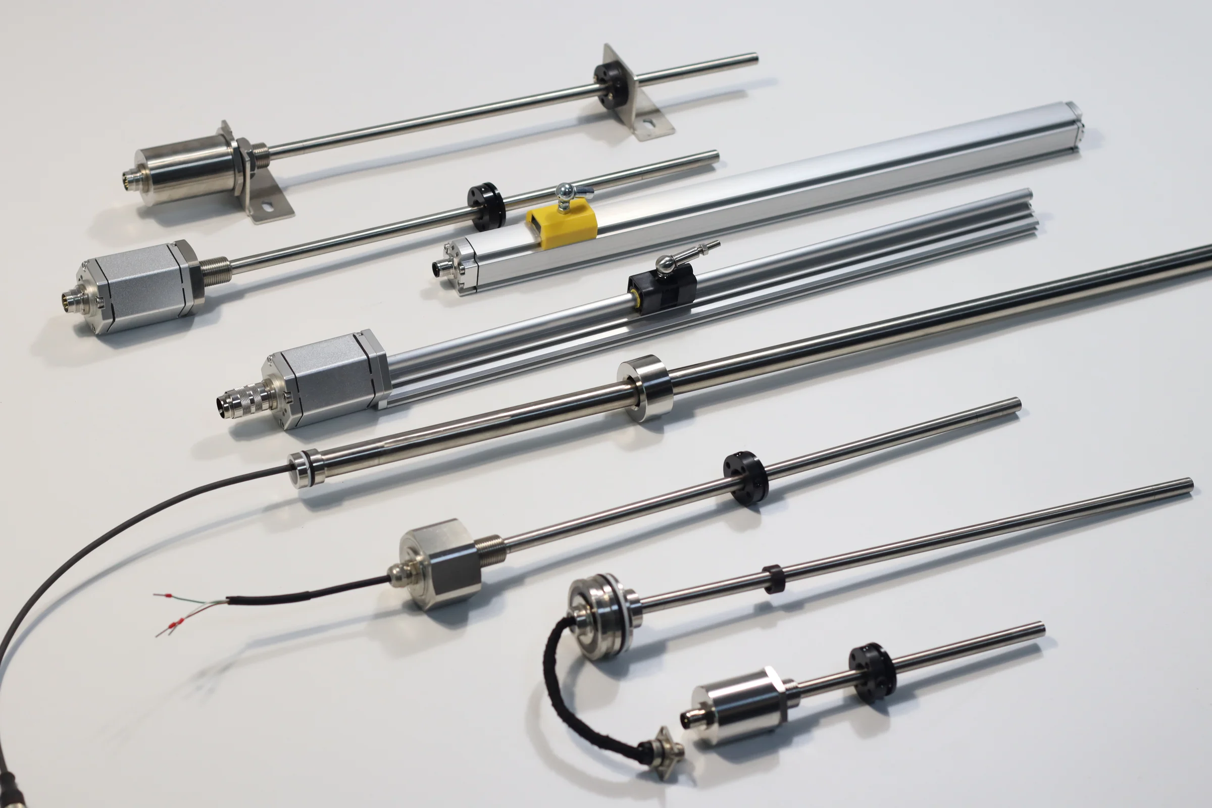
| Magnetostrictive position sensors | SGM-PR10, SGM-PE10, SGM-PF10 | 25–8000 mm | 4–20 mA / 0–10 V / RS485; SSI on SGM-PR10 and SGM-PE10 |
| Compact and slim position sensors | SGM-PE20, SGM-PR40, SGM-PR50 | 25–4000 mm | 4–20 mA / 0–10 V / RS485 |
| Intrinsically safe position sensor | SE-PR30 | 25–4000 mm | 0.5–4.5 V / 0–5 V / 4–20 mA / RS485; 0–10 V on request |
| Magnetostrictive tank level | SGM-LS10 / SGM-LC10 | 25–8000 mm / 25–1000 mm | Analog or RS485 |
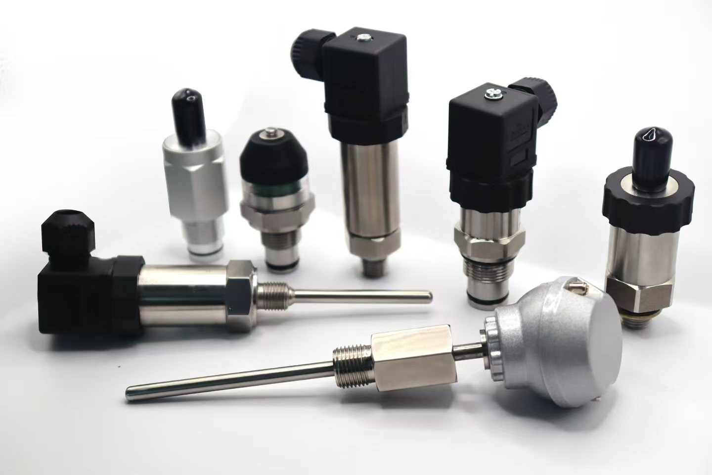
| Pressure transmitters | Standard and high-accuracy | 0–0.1 to 0–400 bar; ±0.25% FS, ±0.1% FS high-accuracy | 4–20 mA / 0–10 V / RS485 Modbus RTU |
| Clamp-on ultrasonic flow meters | Fixed U-series | — | RS485 Modbus selectable; standard on U13 |
| Commercial terms | MOQ 1 piece · samples 1–5 pcs in 5–7 working days · production 3–5 weeks · FOB China · 12-month warranty | ||
Download the one-page datasheet (PDF)
The magnetostrictive position sensor datasheet lists stroke ranges, output options including RS485, supply voltage, housing and IP rating, connectors and the ordering code; the pressure transmitter datasheet covers ranges, accuracy classes and outputs. No registration required.
For outdoor and washdown buses, check the enclosure rating as well as the electronics: the IP code of each housing and connector option is defined under IEC 60529. When replacing an existing sensor, send us the nameplate or specification together with the register list your PLC expects; we confirm a matching model, and you can validate it with 1–5 samples first.
Why does an RS485 Modbus sensor not respond?
- Serial settings mismatch — baud rate, parity and stop bits must be identical on master and sensor; check the factory defaults in the datasheet.
- Wrong or duplicate slave address — two sensors with the same address corrupt each other's replies. Set addresses one sensor at a time before connecting the bus.
- A and B swapped — the most common fault on a new installation.
- Termination missing or doubled — fit 120 Ω only at the two ends of the trunk.
- Timeout too short — at 9600 baud a long reply takes tens of milliseconds; allow for it before the master retries.
- Value wrong but changing — check 32-bit word order and the 0-based vs 1-based register offset.
Frequently Asked Questions
No. RS485 is the electrical layer — a two-wire differential bus — while Modbus RTU is the message protocol that runs on it. A sensor specified as "RS485 Modbus RTU" uses both: RS485 wiring and Modbus RTU frames with slave address, function code, data and CRC.
A standard RS485 segment supports 32 unit loads, and Modbus RTU allows slave addresses 1 to 247. Transceivers rated at a fraction of a unit load raise the device count per segment, and repeaters add further segments; in practice, polling time usually limits a bus before the address range does.
Yes, on any bus of meaningful length: fit one 120 Ω resistor across A and B at each of the two physical ends of the cable. Do not add termination at sensors in the middle of the bus, because extra resistors overload the line drivers.
Up to about 1200 m at low baud rates such as 9600 baud, using shielded twisted-pair cable with correct termination. Higher baud rates shorten the usable length, so long sensor buses usually run at 9600 or 19200 baud.
RS485 output is available on SEGMENsensor magnetostrictive position sensors (25–8000 mm), magnetostrictive tank level sensors, pressure transmitters (0–0.1 to 0–400 bar) and fixed clamp-on ultrasonic flow meters. The register map comes with the datasheet; MOQ is 1 piece and we reply to inquiries within 24 hours.
Last updated · SEGMENsensor Engineering Team