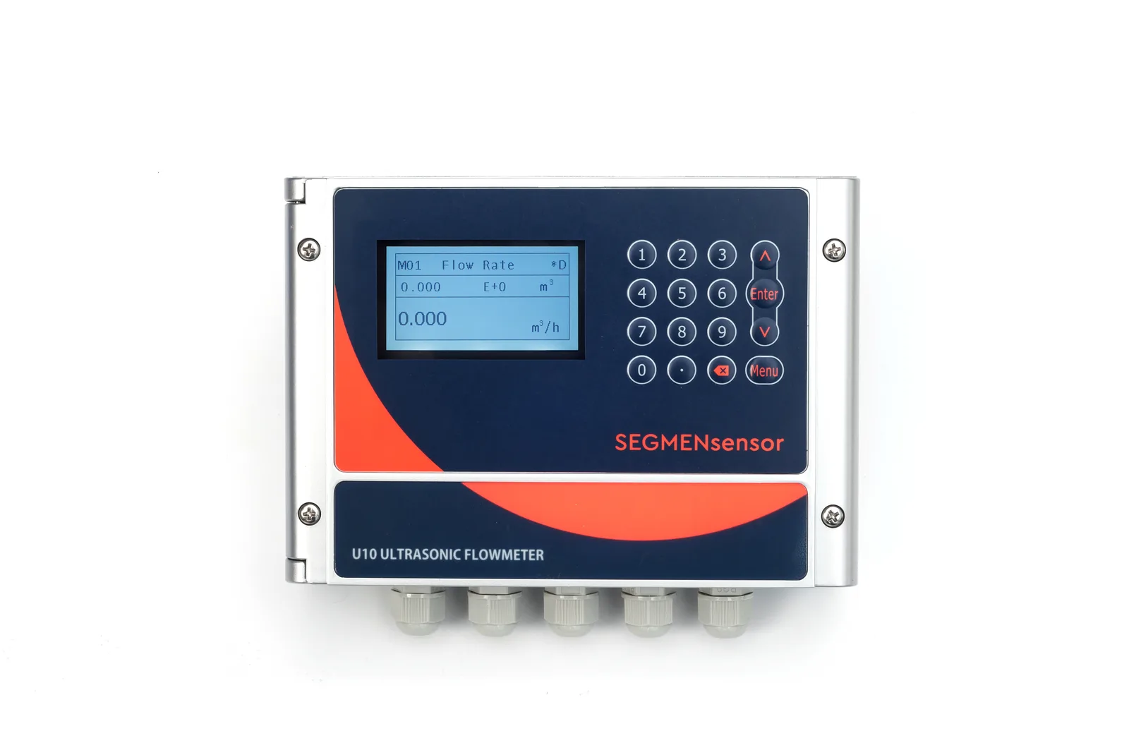
To install a clamp-on ultrasonic flow meter: (1) Select a straight pipe section with ≥10D upstream and ≥5D downstream clear of any elbows, valves, or pumps. (2) Clean and degrease the pipe surface. (3) Apply ultrasonic couplant gel to the transducer faces. (4) Mount the transducers using the manufacturer's spacing guide for your pipe diameter. (5) Enter pipe parameters (OD, wall thickness, material) into the meter. (6) Verify signal strength ≥60% before commissioning.
What Is a Clamp-On Ultrasonic Flow Meter?
A clamp-on ultrasonic flow meter measures liquid flow rate by clamping two transducers to the outside of an existing pipe — no pipe cutting, no process shutdown, no contamination risk. The transit-time method measures the travel time difference between ultrasonic pulses sent upstream and downstream. This time difference is proportional to the flow velocity of the liquid inside the pipe.
Because clamp-on meters make no physical contact with the fluid, they are ideal for retrofitting to existing piping, measuring aggressive chemicals or high-purity liquids, and permanent monitoring where inline meters cannot be installed without a shutdown. The SEGMENsensor U series operates on pipe diameters from DN15 to DN6000 with ±1% accuracy at flow velocities of 0.2–12 m/s.
Before You Start: Site Survey Checklist
- Pipe is full: Transit-time meters require 100% full pipe at the measurement point.
- Liquid is clean: Transit-time works on clean liquids. Heavily aerated or slurry flows require Doppler technology instead.
- Pipe material is acoustically transparent: Steel, stainless steel, copper, PVC, PE/HDPE, CPVC, fiberglass — all work. Concrete lining, thick rubber lining (>6 mm), and severely corroded pipes reduce signal strength.
- Straight run is available: Find a section with ≥10D upstream and ≥5D downstream clear of elbows, valves, reducers, and pumps.
- Pipe dimensions confirmed: Measure outer diameter (OD) and wall thickness with calipers — do not rely on nominal pipe specifications which may differ from actual.
- Temperature within range: Standard transducers rated to 60°C pipe surface; high-temperature versions to 130°C or 200°C.
Step-by-Step Installation Procedure
-
Select and mark the measurement location
Choose a straight pipe run with ≥10× pipe diameter (10D) upstream and ≥5D downstream of the transducer position, clear of all flow disturbances. On a 100 mm (DN100) pipe, this means 1,000 mm upstream and 500 mm downstream. Mark the transducer center-line with a paint marker or tape. Avoid the bottom of the pipe (sediment accumulation) and the top (air pockets) — mount on the side (3 o'clock or 9 o'clock position) for horizontal pipes, or anywhere on vertical pipes with upward flow.
-
Prepare the pipe surface
Clean the pipe surface at both transducer positions. Remove paint, scale, rust, grease, and moisture over a 100 × 100 mm area at each transducer location. Use sandpaper (60–80 grit) to remove flaking rust or thick paint. Wipe clean with isopropyl alcohol or acetone and allow to dry completely. A clean, smooth surface is essential for reliable ultrasonic coupling — this step is the single most common cause of poor signal quality in the field.
-
Determine transducer spacing (V-mode or Z-mode)
Enter the pipe outer diameter, wall thickness, pipe material, and fluid type into the flow meter display. The meter will calculate and display the required transducer spacing in millimetres — this is the exact center-to-center distance along the pipe axis between the two transducers. For most pipes DN15–DN300, V-mode is used (both transducers on the same side of the pipe, signal bounces off the opposite wall). For larger pipes (DN300+) or heavily scaled pipes, switch to Z-mode (transducers on opposite sides of the pipe, signal passes directly across). Mark the transducer positions precisely with calipers and marker.
-
Apply coupling gel and mount the transducers
Apply a 2–3 mm bead of ultrasonic couplant gel (water-soluble silicone-based) to the face of each transducer. Press each transducer firmly against the pipe at the marked positions, squeezing out air bubbles. Secure with the supplied stainless steel strap clamps, tightening evenly on both sides. The transducers must be parallel to each other (not twisted) and at the exact calculated spacing — even a few millimetres of error in spacing will reduce accuracy. For permanent installations, use RTV silicone adhesive couplant instead of gel.
-
Connect the signal cable and power
Connect the coaxial signal cables from each transducer to the labeled ports on the flow meter transmitter (upstream and downstream must match the physical installation orientation). Connect 24 VDC or 85–265 VAC power (depending on the model). Keep signal cables away from high-voltage power cables and variable frequency drives (VFDs) to avoid electromagnetic interference. Maximum cable length is typically 10 m for standard coaxial cable; use shielded twisted-pair cable for longer runs.
-
Verify signal strength and commission
Power on the flow meter and navigate to the signal quality / diagnostic screen. Check the signal strength or S/N ratio indicator. A reading of ≥60% signal strength is required for stable measurement — most meters display a bar graph or percentage. If signal strength is below 60%: (a) re-clean the pipe surface and re-apply couplant gel; (b) verify transducer spacing; (c) try Z-mode if V-mode signal is weak. Once signal strength is acceptable, verify that the displayed flow velocity is physically reasonable for your system and run a zero-flow check (close isolation valves and confirm zero reading before re-opening).
Common Installation Mistakes and How to Avoid Them
| Mistake | Symptom | Fix |
|---|---|---|
| Insufficient straight run | Unstable reading, ±5–10% error | Relocate to longer straight section; use multi-path meter |
| Air in pipe at measurement point | No signal or intermittent signal | Move to a point where pipe is always full; bleed air from system |
| Incorrect pipe OD entered | Systematic offset error (e.g., always 5% high) | Re-measure OD with calipers; re-enter accurate dimension |
| Dirty or painted pipe surface | Low signal strength (<40%) | Sand and clean the surface; re-apply fresh couplant gel |
| Transducers not parallel or twisted | Weak signal, erratic readings | Re-mount transducers with ruler to ensure exact alignment |
| VFD interference on cable | Noisy reading, spikes in trend | Route signal cables away from VFD; use shielded cable; add ferrite cores |
| Bottom-of-pipe mounting on horizontal pipe | Low signal due to sediment layer | Relocate to 3 o'clock or 9 o'clock position on horizontal pipe |
Compatible Pipe Materials and Fluids
Transit-time clamp-on meters work on all clean, single-phase liquids at velocities above 0.2 m/s. The table below summarises compatibility for the most common industrial piping systems:
| Pipe Material | Compatible | Notes |
|---|---|---|
| Carbon steel | ✅ Yes | Standard installation; clean surface required |
| Stainless steel (304/316) | ✅ Yes | Excellent signal propagation |
| Copper | ✅ Yes | Common in HVAC and CDU cooling loops |
| PVC / CPVC | ✅ Yes | Good; use Z-mode for larger diameters |
| PE / HDPE | ✅ Yes | Some signal loss; 10D+ straight run recommended |
| Cast iron | ⚠️ Caution | Works if no thick graphite layer; verify signal strength |
| Fiberglass (GRP/FRP) | ⚠️ Caution | Works on most; signal loss depends on lay-up thickness |
| Rubber-lined pipe | ❌ No (lining >6 mm) | Signal blocked by thick liner; use inline meter |
| Concrete-lined pipe | ❌ No | Signal attenuated by concrete; use Doppler or inline |
- Transit-time (this guide) requires clean, single-phase liquid with no significant gas bubbles, solids, or suspended particles.
- If your fluid is a slurry, heavily aerated, or contains >2% solids by volume, use a Doppler ultrasonic meter instead — the reflective particles are required for Doppler signal return.
- SEGMENsensor U series are transit-time meters designed for clean water, coolants, oils, chemicals, and similar clean liquids.
Frequently Asked Questions
Clamp-on transit-time ultrasonic flow meters work on most pipe materials that transmit ultrasound: carbon steel, stainless steel, cast iron, copper, PVC, CPVC, PE/HDPE, and fiberglass. They do not work reliably on concrete-lined pipes, heavily corroded pipes, or pipes with rubber lining thicker than 6 mm. The pipe wall must be solid and uniform for the ultrasonic signal to pass cleanly.
Standard installation requires at least 10× pipe diameter (10D) of straight run upstream and 5D downstream of the measurement point, clear of elbows, tees, valves, reducers, or pumps. For single-beam meters near control valves, 15D upstream is recommended. Always measure from the nearest flow disturbance, not from the beginning of the straight section.
Standard couplant is a water-soluble silicone-based gel. For permanent installations, RTV silicone adhesive creates a permanent acoustic bond. For high-temperature applications (pipe surface above 60°C), use a high-temperature couplant rated for the pipe surface temperature. Never use water-based gel on pipes above 60°C — it dries out and loses coupling effectiveness.
No. Transit-time clamp-on meters require the pipe to be completely full of liquid at the measurement point. If the pipe is partially filled or contains air pockets, the signal will be attenuated or lost entirely. For partially filled pipes, use an open-channel flow meter or Doppler ultrasonic meter instead.
V-mode mounts both transducers on the same side of the pipe, with the signal bouncing off the opposite pipe wall. This is standard for most pipe sizes DN15–DN300. Z-mode mounts transducers on opposite sides of the pipe, with the signal passing directly across. Use Z-mode for large pipes (DN300+) or when V-mode signal strength is below 60%.
Check: (1) Signal strength ≥60% on the meter display. (2) Measured velocity is reasonable for your pipe size and pump. (3) Zero-flow check — close isolation valves and confirm zero reading. (4) Cross-check with bucket-and-stopwatch test or a known-accurate reference meter if available.
SEGMENsensor U series clamp-on meters measure 0.2–12 m/s (bidirectional). The optimal accuracy range is 0.5–8 m/s. Below 0.2 m/s, the transit-time difference is too small to resolve accurately. Above 12 m/s, turbulence reduces accuracy.
Clamp-on meters are factory calibrated. Field calibration is not required if pipe OD, wall thickness, and material are entered correctly. Errors in pipe dimension inputs directly cause systematic flow reading errors. Annual signal quality checks are recommended; full recalibration is only needed if the pipe is modified or replaced.
Yes, with precautions. Remove insulation at the measurement section. SEGMENsensor U transducers are rated to 130°C pipe surface (200°C high-temperature version). Use high-temperature couplant for surfaces above 60°C. Never mount transducers through insulation material — acoustic coupling requires direct contact with the bare pipe surface.