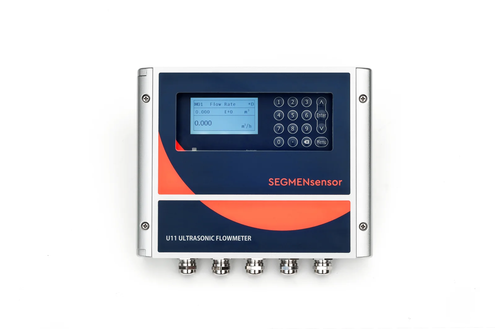
For power plant water systems, use a transit-time clamp-on ultrasonic flow meter on full pipes of clean water: circulating and auxiliary cooling water, cooling tower make-up, demineralized make-up water and condensate. Choose the U11 for mains above 1200 mm or where ±0.5% is needed, and match the sensor (A2, H1A or H2A) to the line temperature.
Why Do Power Plants Use Clamp-On Ultrasonic Flow Meters?
Because the meter is added from outside the pipe while the unit keeps running. A clamp-on ultrasonic flow meter times ultrasonic pulses sent with and against the flow between two transducers strapped to the pipe wall; the transit-time difference gives velocity, and the pipe inner area gives volume flow. The principle for liquids in closed conduits is covered by ISO 12242 — Measurement of fluid flow in closed conduits: ultrasonic transit-time meters for liquid.
In a generating plant that matters for three reasons. First, the largest water lines — the circulating water mains between the pumps, condenser and cooling tower or intake — are too big and too critical to cut for an inline meter. Second, many points were never metered at all, and the need appears later: a condenser performance check, a cooling tower water balance, or a request to report how much cooling water is drawn. In the United States, for example, cooling water intake structures at power plants are regulated under the Clean Water Act, as explained on the US EPA Cooling Water Intakes page. Third, a clamp-on meter has no wetted parts and no pressure drop, so it adds no leak point and no pumping cost.
Typical Measuring Points in a Thermal or CHP Plant
The table lists the water lines where we are most often asked for a clamp-on meter. Pipe sizes and media are typical plant values for orientation; model data are from the SEGMENsensor product page and datasheet.
| Measuring point | Typical pipe | Medium and temperature | Suggested SEGMENsensor model | Confirm before ordering |
|---|---|---|---|---|
| Circulating (main) cooling water, pump discharge to condenser and return | Large steel mains, often above DN1200; may be lined | Cooling water near ambient temperature | U11 (15–5000 mm, ±0.5%), Z-mode, A2 sensors (−40 to +80 °C) | Actual OD and wall, liner type and thickness, access to both sides of the pipe, straight run |
| Auxiliary / closed cooling water (bearing, oil and generator coolers) | Steel, DN100–DN600 | Treated or demineralized water, usually within +80 °C | U10 or U10S (±1%), V-mode; U11 if ±0.5% is needed | Maximum water temperature against the A2 rating; 4-20 mA or Modbus to the DCS |
| Cooling tower make-up and blowdown | Steel, ductile iron or PE | Make-up: clarified water. Blowdown: may carry solids | U10 / U10S, or U11 on large pipes | Solids and air in the blowdown; full pipe at the measuring point |
| Boiler make-up and demineralized water | Stainless or carbon steel, DN50–DN300 | Clean water near ambient temperature | U10S or U11; pulse output for totalizing | Small pipes below 25 mm need U10S, U10S PRO or U11 (from 15 mm) |
| Condensate, after the condensate pumps | Carbon steel, insulated | Hot water; check the maximum temperature | U10 series or U11 with H1A sensors (to +130 °C) | Measure on the discharge side, away from flashing; insulation removal at the section |
| Deaerator outlet and low-pressure feedwater | Carbon steel, insulated | Hot water; must stay within +180 °C including transients | U10 series or U11 with H2A sensors (to +180 °C) | Highest temperature in start-up and upset; if it can exceed +180 °C, the point is not suitable |
| CHP heat network supply and return | Steel, insulated | Hot water; heat (energy) metering | Energy (BTU) version with PT1000 temperature sensors; H1A sensors to +130 °C | Supply and return temperatures; Modbus register list for the metering system |
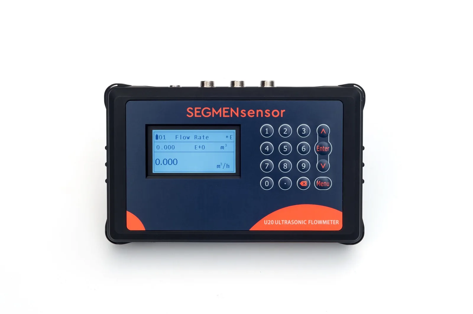
| Pump tests and checking existing meters | Any of the above, 25–1200 mm | Clean water | U20 portable (P2 to +80 °C, P2H to +130 °C) | Pipe size range of the transducer pair supplied |
Installation Difficulties in Power Plants and How to Handle Them
Large mains with short straight runs
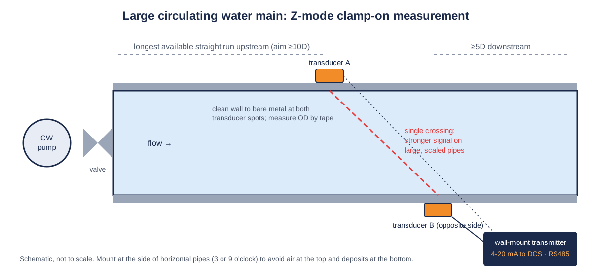
On a large circulating water main, 10D upstream can mean many metres of pipe that the layout simply does not have. Use Z-mode (transducers on opposite sides), pick the longest straight section available, keep away from the pump discharge, butterfly valves and tees, and check signal strength and quality on the meter's status page. Where the section is a compromise, a second reading at another position with the U20 portable clamp-on flow meter shows whether the profile is disturbed.
Old pipes: scale, rust and internal linings
Cooling water pipes collect scale and corrosion. Clean the outer wall to bare metal at both transducer spots, measure the real outer diameter with a circumference tape and the wall with a thickness gauge, and enter any internal liner material and thickness. If the signal stays weak, move to a section with a better wall rather than accepting a low-quality reading.
Hot, insulated lines
Condensate, feedwater and heat-network lines are insulated. Open the insulation only at the measuring section, select H1A (+130 °C) or H2A (+180 °C) sensors by the highest line temperature, use couplant rated for that temperature, and keep the transducer cable off the hot surface.
Electrical noise near large motors and drives
Pump houses are full of large motors and variable-frequency drives. Run the transducer and signal cables in their own tray away from motor power cables, use shielded cable for 4-20 mA and RS485, and earth the shield at one end.
Pits, trenches and outdoor pipe racks
Transducers are IP68 and the U10-series transmitter is IP65, with the IP code defined in IEC 60529 — Degrees of protection provided by enclosures (IP Code). In pits that can flood, mount the transmitter above flood level and run the IP68 transducer cable down to the pipe.
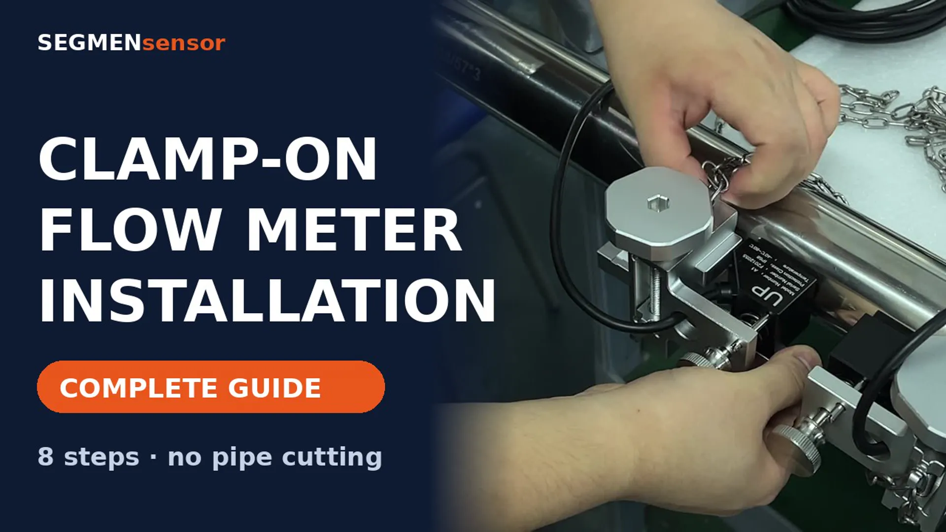
The full mounting procedure, including V-, Z- and W-mode spacing, is in the clamp-on flow meter installation guide and the installation video with chapters.
Send your plant line data for a flow meter selection
Tell us the measuring point, pipe OD, wall thickness and material, any liner, maximum water temperature, available straight run, output signal to the DCS and quantity. OEM volume supply · samples 1–5 pcs in 5–7 working days · production lead time and MOQ confirmed with the quotation · quotation within 24 hours.
Which Power Plant Lines Are Not Suitable for a Transit-Time Clamp-On Meter?
Lines that carry steam, two-phase flow, high solids or water above +180 °C are not suitable. Specifically:
- High-pressure feedwater above +180 °C, for example after the high-pressure heaters: outside the highest sensor rating (H2A).
- Steam, wet steam and flashing drains such as heater drains: transit-time meters measure single-phase liquids only.
- Slurries such as ash sluicing water and flue gas desulfurization (FGD) limestone slurry: high solids scatter the ultrasonic signal.
- Partially full pipes such as gravity returns, siphon outlets and seal-well discharges: the pipe must be full at the measuring point.
- Water with heavy entrained air, for example directly at a pump suction with vortexing or just after a long free fall.
- Concrete and thick non-metallic pipe walls: assess first; usually a steel section of the same line is the better measuring point.
If you are unsure whether a medium carries too much air or solids, read transit-time vs Doppler ultrasonic flow meters and describe the medium in your inquiry.
Specifications That Matter for Power Plant Water
The values below are taken from the SEGMENsensor ultrasonic flow meter product page and datasheet. Compare every model in the U10 to U20 model comparison.
| Parameter | U10 / U10S / U10S PRO | U11 | U20 portable |
|---|---|---|---|
| Pipe size | 25–1200 mm (U10) · 15–1200 mm (U10S, U10S PRO) | 15–5000 mm | 25–1200 mm |
| Accuracy | ±1% | ±0.5% | ±1% |
| Repeatability | 0.2% | 0.1% | — |
| Velocity range | ±0.03 to ±5 m/s | ±0.01 to ±12 m/s | ±0.01 to ±12 m/s |
| Sensor temperature | A2 −40 to +80 °C · H1A to +130 °C · H2A to +180 °C | Same sensors as the U10 series | P2 −40 to +80 °C · P2H to +130 °C |
| Outputs | Choose two: 4-20 mA, pulse (OCT), relay, RS232 / RS485 Modbus; HART optional | Choose two: 4-20 mA, pulse (OCT), relay, RS232 / RS485 Modbus; HART optional | Choose two: 4-20 mA, RS485 Modbus, OCT, relay; SD card logging |
| Power supply | 10–36 V DC; 90–245 V AC optional | 90–245 V AC or 10–36 V DC | Rechargeable 3000 mAh lithium battery, about 16 h per charge |
| Protection | Transmitter IP65, sensors IP68 | Sensors IP68 | Sensors IP68 |
| Certification | CE, UKCA | ||
Download the one-page datasheet (PDF)
Pipe size ranges, accuracy, transducer types and temperature ratings, outputs, power supply, enclosure ratings and ordering code for the SEGMENsensor clamp-on ultrasonic flow meter range. No registration required.
Portable Checks: Pump Tests and Meter Verification
Plant engineers often need a flow figure for a few hours rather than permanently: a circulating water pump test after an overhaul, a check of an existing inline meter that drifts, or a survey before deciding where a fixed meter belongs. The U20 portable meter straps on in minutes, logs flow to an SD card and covers 25–1200 mm; for mains above 1200 mm, a fixed U11 is the right choice.
How Do You Connect the Meter to the DCS?
Use 4-20 mA for the flow value to a DCS analogue input and RS485 Modbus for flow, totalizer and diagnostics. On the U10 series and U11 you choose two outputs from 4-20 mA, pulse (OCT), relay and RS232 / RS485 Modbus, with HART as an option. A pulse output feeds a totalizer for make-up water accounting, and a relay can raise a low-flow alarm on an auxiliary cooling water loop. The same Modbus approach is used for building systems in our data center cooling water flow monitoring guide.
What Affects the Quotation?
We do not publish list prices because the configuration drives the quotation: pipe size range and transducer type, temperature rating, accuracy class, outputs, enclosure and protection rating, any project certification and quantity. Quotations are FOB China and exclude international freight and import duties or taxes; payment is 100% T/T in advance, and meters carry a 12-month warranty.
Get a clamp-on flow meter for your plant water system
U11 for large circulating water mains, U10 series for auxiliary lines, U20 for pump tests. OEM volume supply · samples 1–5 pcs in 5–7 working days · production lead time and MOQ confirmed with the quotation · quotation within 24 hours. Download the clamp-on flow meter datasheet (PDF).
Frequently Asked Questions
Yes. The SEGMENsensor U11 covers pipes from 15 to 5000 mm with ±0.5% accuracy and 0.1% repeatability. On large mains the transducers are usually mounted in Z-mode, on opposite sides of the pipe, at the longest straight section available.
Only where the water stays within the sensor rating. Make-up and demineralized water use standard A2 sensors (−40 to +80 °C), condensate usually H1A (to +130 °C), and low-pressure feedwater H2A (to +180 °C). High-pressure feedwater above +180 °C is outside the rating and is not suitable for our clamp-on meters.
Yes. The transducers are strapped to the outside of the pipe, so there is no cutting, welding or draining. You need access to the pipe surface at the measuring section, and on insulated lines the insulation is opened locally.
On the U10 series and U11 you choose two of 4-20 mA, pulse (OCT), relay and RS232 / RS485 Modbus, with HART as an option. Most plants take 4-20 mA into a DCS analogue input and use RS485 Modbus for totalizer and diagnostic data.
Yes, on pipes from 25 to 1200 mm. The U20 portable meter is specified at ±1% with a velocity range of ±0.01 to ±12 m/s and logs to an SD card, so it can run alongside an existing meter for a comparison over a full load cycle.
Samples of 1–5 pcs ship in 5–7 working days. Production lead time and MOQ are confirmed with the quotation, which we send within 24 hours on working days, FOB China.