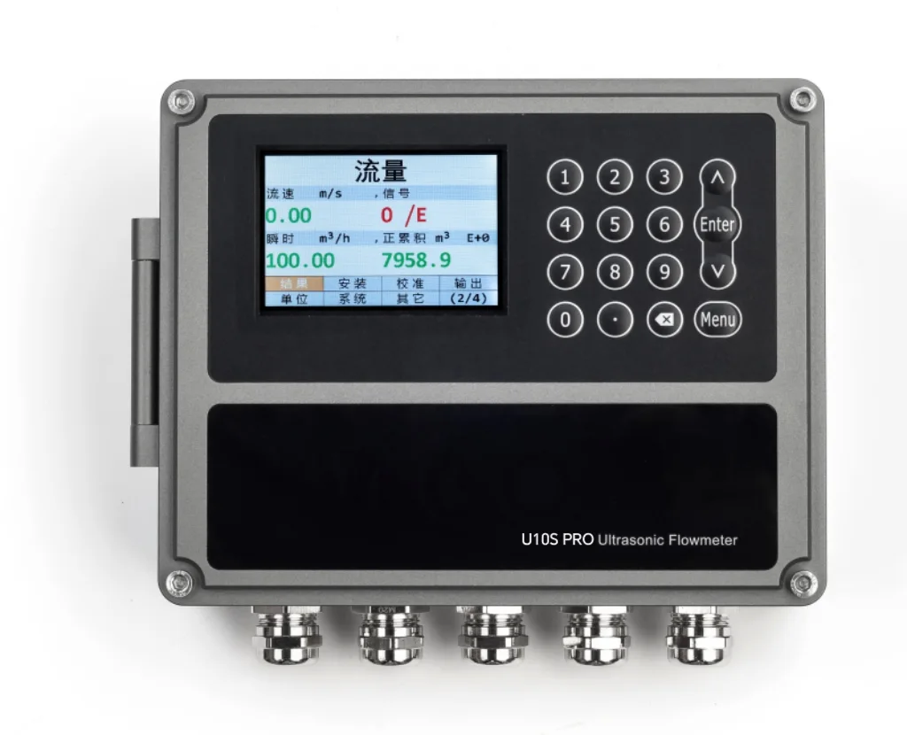
Use a U10S PRO or U11 on the injection pump discharge header and on individual well lines after the distribution manifold, a U11 on source and treated water mains, a U12 at remote well sites on DC power, and the U20 portable meter to check manifold readings and to trial treated produced water. Enter the real wall thickness of high-pressure pipe. Multiphase wellhead flow, raw produced water, crude oil, dosing lines and anything inside a classified hazardous area are not suitable.
Where Does a Clamp-On Meter Fit in an Oilfield Water Injection System?
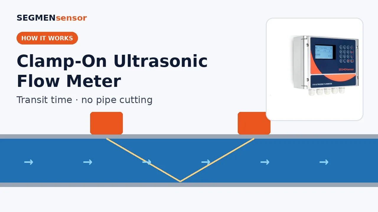
On the water side of the system — from the source wells to the injection wellheads — rather than on the production side. A clamp-on ultrasonic flow meter sends ultrasonic pulses through the pipe wall with and against the flow; the transit-time difference gives velocity and the inner area of the pipe gives volume flow. The method for liquids in closed conduits is described in ISO 12242 — Measurement of fluid flow in closed conduits: ultrasonic transit-time meters for liquid. Injection engineers ask for it for one reason above all: the transducers sit outside the pipe, so a high-pressure injection line gets no new tapping, flange or seal, and a meter can be added or moved without a shutdown.
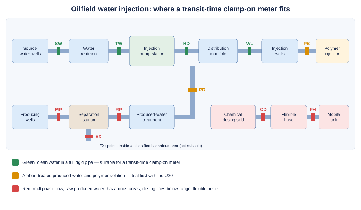
The good points are the source water line, treated water leaving the water plant, the discharge header of the injection pumps and each well line downstream of the distribution manifold, where well-by-well injection rates are allocated. Produced water that is treated and returned for reinjection is the same kind of disposal and enhanced-recovery fluid that the US EPA describes for Class II oil and gas related injection wells; it is measurable in many plants, but residual oil, solids and gas mean it is trialled first. Multiphase flowlines from producing wells and raw produced water leaving the separator are not transit-time applications.
Typical Measuring Points in a Water Injection System
The table lists the lines where injection, production and facility engineers most often ask for a clamp-on meter. Pipe sizes and temperatures are typical values for orientation only; model data are from the SEGMENsensor product page and datasheets. We confirm the model from your pipe and liquid data.
| Measuring point | Typical pipe | Medium · temperature | Suggested model | Confirm before ordering |
|---|---|---|---|---|
| Source water line (water wells or surface water to the plant) | Carbon steel or HDPE, DN100–DN400 | Fresh or brackish water, ambient | U11 (15–5000 mm, ±0.5%) | Pipe material and any internal lining; straight run away from the transfer pumps |
| Treated injection water leaving the water plant | Carbon steel, lined steel or GRP, DN100–DN300 | Filtered water, ambient to warm | U11 or U10S PRO (±1%) | Lining type and thickness; GRP and lined pipe: trial with the U20 first |
| Injection pump discharge header | Thick-wall seamless steel, DN100–DN200 | Injection water at high pressure | U11 (±0.5%) or U10S PRO | Measured OD and wall thickness (schedule); straight run after the pumps and check valves |
| Individual injection well line after the distribution manifold | Thick-wall seamless steel, DN40–DN80 | Injection water at high pressure | U10S PRO (15–1200 mm) per well; U12 (DN15–DN65) where the wall is in range | Wall thickness; lowest daily injection rate; output to the RTU or SCADA |
| Treated produced water returned for reinjection | Carbon steel, often with internal scale, DN80–DN250 | Produced water after oil removal and filtration, often 40–80 °C | Trial with the U20 first; then U11 (A2 sensors −40 to +80 °C, H1A to +130 °C) | Residual oil and solids; gas breakout; internal scale or deposits; water temperature |
| Polymer solution to injection wells | Steel or stainless, DN25–DN80 | Viscous polymer solution | Trial with the U20 first | Viscosity at line temperature; whether the signal holds over a full day |
| Utility water at gathering and injection stations | Steel or PVC, DN25–DN100 | Fire water make-up, cooling and service water | U12 (DN15–DN65) or U10S PRO | Hazardous-area classification of the room; power supply |
Why Does High-Pressure Injection Pipe Need Extra Care?
Because the meter converts velocity to flow with the inner area you enter, and high-pressure pipe has much thicker walls than standard pipe of the same nominal size. Take a 2-inch well line in Schedule 160 pipe: 60.3 mm OD with an 8.74 mm wall gives a 42.82 mm bore. If it were entered as Schedule 40 (3.91 mm wall, 52.48 mm bore), the meter would read about 50% high, because (52.48 / 42.82)² ≈ 1.50 (calculated value). So measure the OD with a tape or caliper, measure the wall with an ultrasonic thickness gauge rather than assuming the schedule, and enter any internal lining with its thickness.
Thick steel walls, internal coatings, GRP and scale also attenuate the ultrasonic signal more than a clean standard-wall pipe. Check the signal strength and quality on the status page after mounting, and if a line is in doubt, clamp the U20 on it first. The U20 portable meter logs flow, signal strength and quality, so a weak signal shows up before a fixed meter is ordered.
Installation Difficulties at Injection Stations and Well Sites
Short straight runs at manifolds
Distribution manifolds pack valves, chokes and elbows into a skid. Keep about 10D of straight pipe upstream and 5D downstream where possible — on a DN50 well line about 500 mm and 250 mm — and stay away from control valves and chokes, which disturb the flow profile. The full procedure is in the clamp-on flow meter installation guide.
Scale, corrosion and old coatings on the pipe
Produced water lines carry scale and deposits inside, and older pipes have rust or coating outside. Mount on a clean section: remove loose paint and rust under the transducer footprint and use couplant. Inside scale reduces the real bore and the signal; where it is heavy, choose a newer or recently cleaned pipe section.
Outdoor sites: sun, cold and remote power
Transducers are IP68 and the U10-series transmitter is IP65. Put the transmitter in the station cabinet or a sunshade enclosure; on the U10 series and U11 the sensor cable is 9 m as standard and up to 274 m on order. At remote wells, the U12 runs on 10–24 V DC from the site's solar or battery supply, with LoRa or 4G customizable for telemetry.
Gas breakout in produced water
Produced water can release dissolved gas where pressure drops, for example after a control valve or at a high point. Mount on the pump discharge side, at the side of horizontal pipes (3 or 9 o'clock), and away from high points. The U11 rides through intermittent bubbles or impurities lasting up to 5 seconds; a line that carries gas continuously is not a clamp-on measuring point.
Hazardous-area classification
Injection stations that handle produced water, and anything near wellheads, separators and tank batteries, may be classified as hazardous areas under IEC 60079-10-1 — Explosive atmospheres: classification of areas, explosive gas atmospheres or local equivalents. SEGMENsensor flow meters have no explosion-protected model, so check the site's area classification drawing first and place both transducers and transmitter only where the classification is non-hazardous.
Send your injection header or well line data for a flow meter selection
Tell us the measuring point (source water, treated water, pump header, well line, produced water), pipe OD and measured wall thickness, material and lining, water type and temperature, daily injection rate range, straight run, power at the site, output to the RTU, PLC or SCADA, the area classification of the location and the quantity. OEM volume supply · samples 1–5 pcs in 5–7 working days · production lead time and MOQ confirmed with the quotation · quotation within 24 hours.
How Do You Check Well-by-Well Injection Rates?
Convert each well's daily rate into velocity for the real bore and compare it with the model's range. In the 42.82 mm bore of a 2-inch Schedule 160 line, a well injecting 100 m³/d runs at about 0.80 m/s and a low-rate well at 20 m³/d at about 0.16 m/s — both inside the U10S PRO range of ±0.03 to ±5 m/s. The U10S PRO lower limit of 0.03 m/s corresponds to about 3.7 m³/d in that bore, so very low-rate wells should be checked against it. On the header, 1500 m³/d in a DN150 Schedule 80 pipe (146.3 mm bore) is about 1.0 m/s (all calculated values from the bores given).
For allocation checks, clamp the U20 on each well line in turn and compare its reading with the manifold meter; the difference shows which wells need attention. For permanent monitoring, use 4-20 mA into the RTU or PLC, read flow and the totaliser over RS485 Modbus, and use the relay as a low-flow alarm when a well stops taking water. HART is optional on the U10, U10S PRO and U11.
Which Oilfield Lines Are Not Suitable?
Multiphase flow, raw produced water, crude oil, gas, dosing lines below the model range, flexible hoses and any point inside a classified hazardous area are not suitable for a SEGMENsensor clamp-on meter. Specifically:
- Wellhead flowlines and test lines with oil, water and gas together: transit-time meters measure a single liquid in a full pipe, not multiphase flow.
- Raw produced water from the separator, before oil removal and filtration: oil droplets, solids and gas scatter the ultrasonic pulse.
- Crude oil, and heavy or waxy oil: not on the datasheet liquid list. Diesel and gasoline are listed, but fuel and crude lines normally run through classified areas.
- Any location inside a classified hazardous area: SEGMENsensor flow meters, including the battery-powered U20, have no explosion-protected model.
- Chemical injection and dosing lines (corrosion and scale inhibitor, demulsifier): flows are far below the lowest velocity in the smallest pipe size.
- Gas lines and steam: the meters are for liquids only. Flexible hoses on mobile units are also excluded; the pipe list covers rigid pipe only.
Specifications That Matter for Injection Water Lines
The values below are taken from the SEGMENsensor ultrasonic flow meter product page and datasheets. Compare every model in the U10 to U20 model comparison.
| Parameter | U10S PRO / U11 | U12 | U20 portable |
|---|---|---|---|
| Pipe size | 15–1200 mm (U10S PRO) · 15–5000 mm (U11) | DN15–DN65, minimum inner diameter 12 mm | 25–1200 mm (1–48 in); F1 / F1H sensors DN15–DN40 |
| Accuracy | ±1% (U10S PRO) · ±0.5% (U11) | ±2% (±1% after calibration) | ±1% |
| Flow velocity | ±0.03 to ±5 m/s (U10S PRO) · ±0.01 to ±12 m/s (U11) | 0.03–10 m/s | ±0.01 to ±12 m/s |
| Liquid temperature | A2 −40 to +80 °C · H1A to +130 °C · H2A to +180 °C | 0–65 °C · 0–115 °C option | P2 −40 to +80 °C · P2H to +130 °C |
| Outputs · data | Choose two: 4-20 mA, pulse (OCT), relay, RS232 / RS485 Modbus; HART optional | Choose two: 4-20 mA, RS485 Modbus, OCT pulse, relay; LoRa or 4G customizable | SD card up to 32 GB, logging interval 1–99999 s |
| Power | 10–36 V DC (90–245 V AC optional on U10S PRO; either on U11) | 10–24 V DC | 3000 mAh rechargeable lithium battery, about 16 hours per charge |
| Liquids · certification | Single, acoustically conductive liquids in a full pipe (the datasheets list water, seawater, diesel, gasoline and others) · CE, UKCA · no explosion-protected model | ||
Download the one-page datasheet (PDF)
Pipe size ranges, accuracy, transducer types and temperature ratings, outputs, power supply, enclosure ratings and ordering code for the SEGMENsensor clamp-on ultrasonic flow meter range. No registration required.
How Do You Trial a Produced Water Line Before Fixing a Meter?
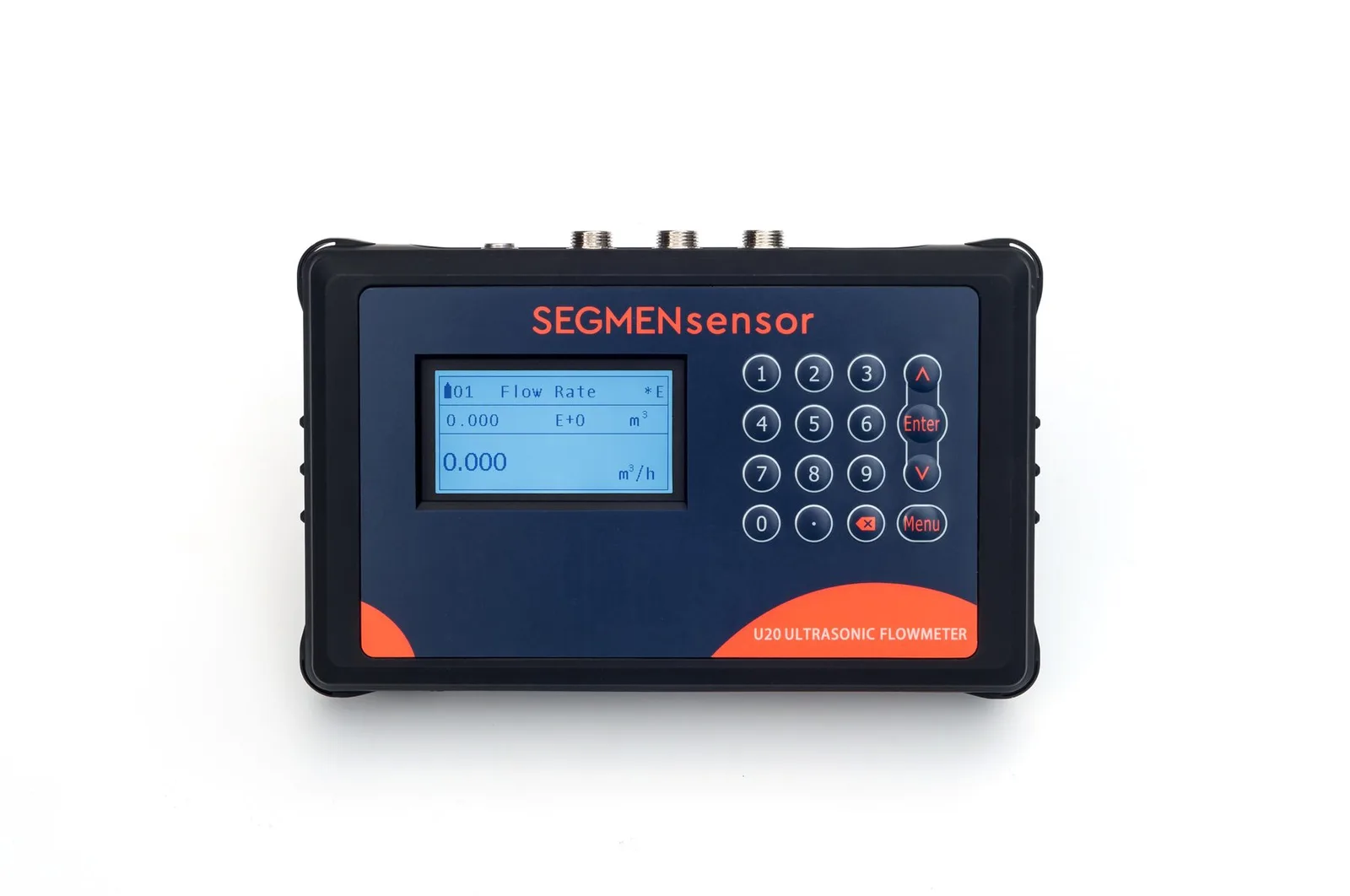
Clamp the U20 portable clamp-on flow meter on the candidate line, in a non-hazardous location, and log at least one full operating day, including pump changeovers and any backwash of the filters upstream. Record flow, signal strength and quality on the SD card; P2H sensors cover produced water up to +130 °C. If the signal holds through the whole period, a fixed U11 will work there; if it drops whenever the oil content rises or gas breaks out, measure on the treated water line downstream instead. The U20 setup is shown in the U20 setup video.
Related Pages
Pump discharge checks and flow verification against installed meters are covered in clamp-on flow meters for pump station flow verification, treated effluent and reuse water in the treated effluent and reuse water guide, and corrosive process liquids in the chemical plant guide. Why gassy or dirty liquids are a different measuring problem is explained in transit-time vs Doppler ultrasonic flow meters.
What Affects the Quotation?
We do not publish list prices because the configuration drives the quotation: fixed, one-piece or portable, pipe size range and transducer type, temperature rating, accuracy class, outputs and telemetry, power supply, cable length and quantity. Quotations are FOB China and exclude international freight and import duties or taxes; payment is 100% T/T in advance, and meters carry a 12-month warranty.
Get a clamp-on flow meter for injection water and reinjection lines
U10S PRO and U11 for pump headers and well lines, U11 for water plant mains, U12 for remote well sites on DC power, U20 for well-by-well checks and produced water trials. OEM volume supply · samples 1–5 pcs in 5–7 working days · production lead time and MOQ confirmed with the quotation · quotation within 24 hours. Download the clamp-on flow meter datasheet (PDF).
Frequently Asked Questions
Yes, where the injection water is clean and fills the pipe: source water, treated injection water, the pump discharge header and individual well lines after the distribution manifold. The transducers stay outside the pipe, so the high-pressure line is not cut or tapped.
Not for the meter itself, because the transducers sit on the outside of the pipe. It matters for the pipe data: high-pressure lines have thick walls, and the real wall thickness must be entered. A 2-inch Schedule 160 line entered as Schedule 40 reads about 50% high (calculated value).
Treated produced water after oil removal and filtration often can, but trial it first with the U20 portable meter, because residual oil, solids, gas and internal scale weaken the signal. Raw produced water straight from the separator is not suitable.
No. SEGMENsensor flow meters have no explosion-protected model and no Ex certification. Use them only at points that your site's area classification places outside any hazardous zone.
Diesel and gasoline are on the datasheet liquid list; crude oil is not, and multiphase flow from the wellhead cannot be measured. Fuel and crude lines usually run through classified hazardous areas, where these meters must not be installed.
Samples of 1–5 pcs ship in 5–7 working days. Production lead time and MOQ are confirmed with the quotation, which we send within 24 hours on working days, FOB China.