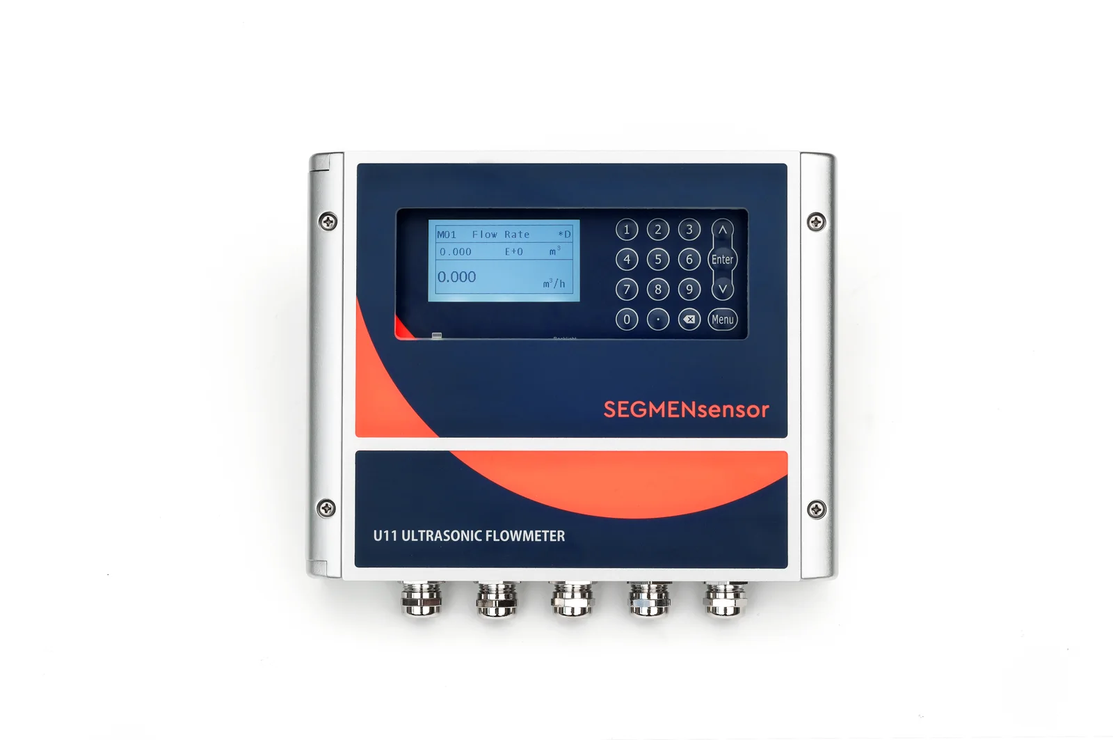
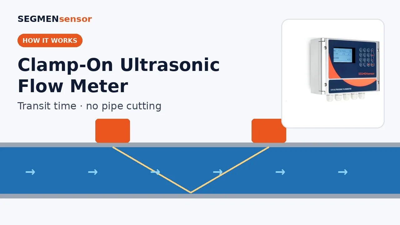
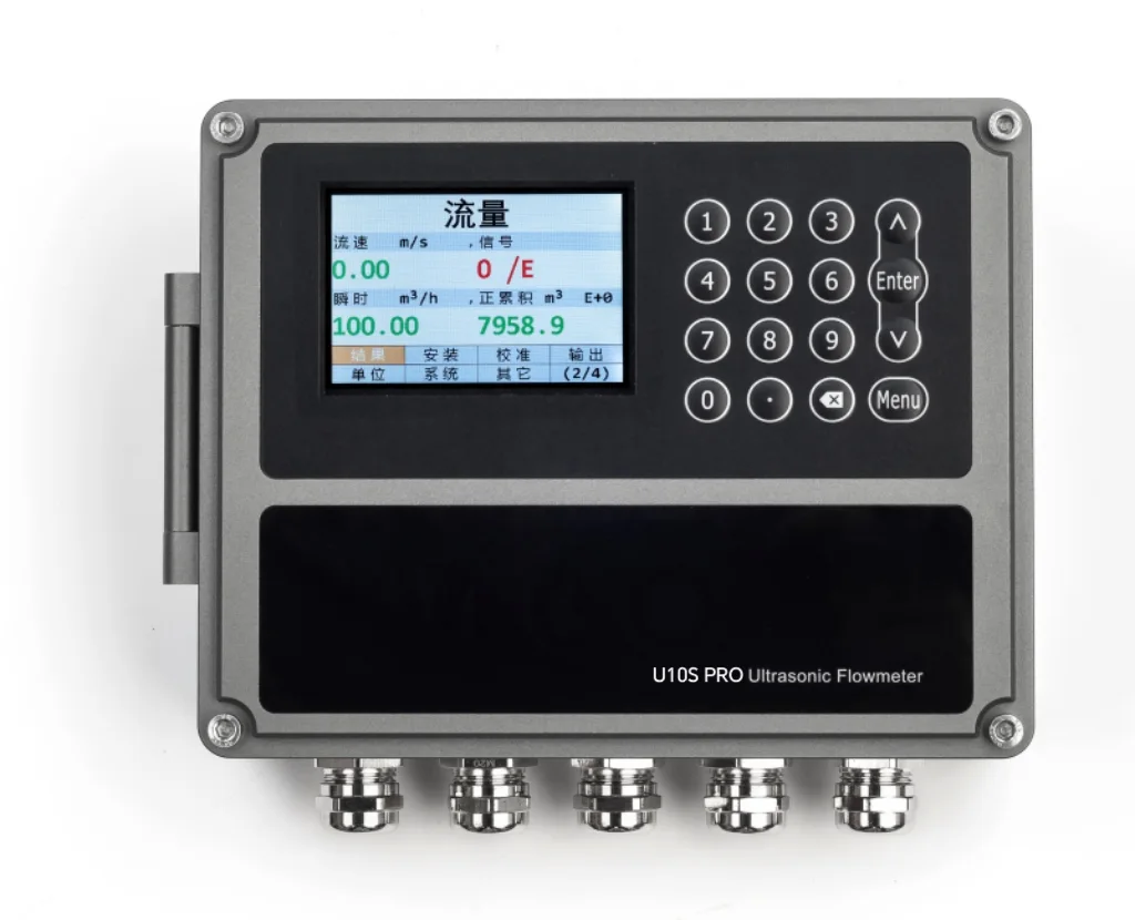
Use a fixed U11 (15–5000 mm, ±0.5%) on the pumped treated-effluent or outfall force main, U10S / U10S PRO (±1%) on reuse water pump lines and user branches, and the U20 portable meter to trial a doubtful line or to cross-check an installed meter. Measure only on full pressure pipe after filtration or disinfection. Raw sewage, mixed liquor, sludge lines and partly full gravity outfalls are not suitable for transit-time clamp-on meters.
Where Does a Clamp-On Meter Fit in a Wastewater Plant?
At the clean end, after secondary treatment and filtration, where the water is in a full pressure pipe. A clamp-on ultrasonic flow meter times ultrasonic pulses sent with and against the flow through the pipe wall; the transit-time difference gives velocity, and the pipe's inner area gives volume flow. The method for liquids in closed conduits is described in ISO 12242 — Measurement of fluid flow in closed conduits: ultrasonic transit-time meters for liquid. The pulse has to cross the liquid, so suspended solids and gas bubbles are what limit it, not the pipe.
That gives a simple rule along the treatment train: the further downstream, the better the signal. Treated effluent pumped to the outfall, reuse (reclaimed) water sent to cooling towers, process users or a third-party network, and plant service water drawn from the effluent tank are typical clamp-on points. Inlet works, mixed liquor, sludge and return sludge lines are not. Secondary clarifier effluent before the filters sits in between and should be trialled before a fixed meter is ordered.
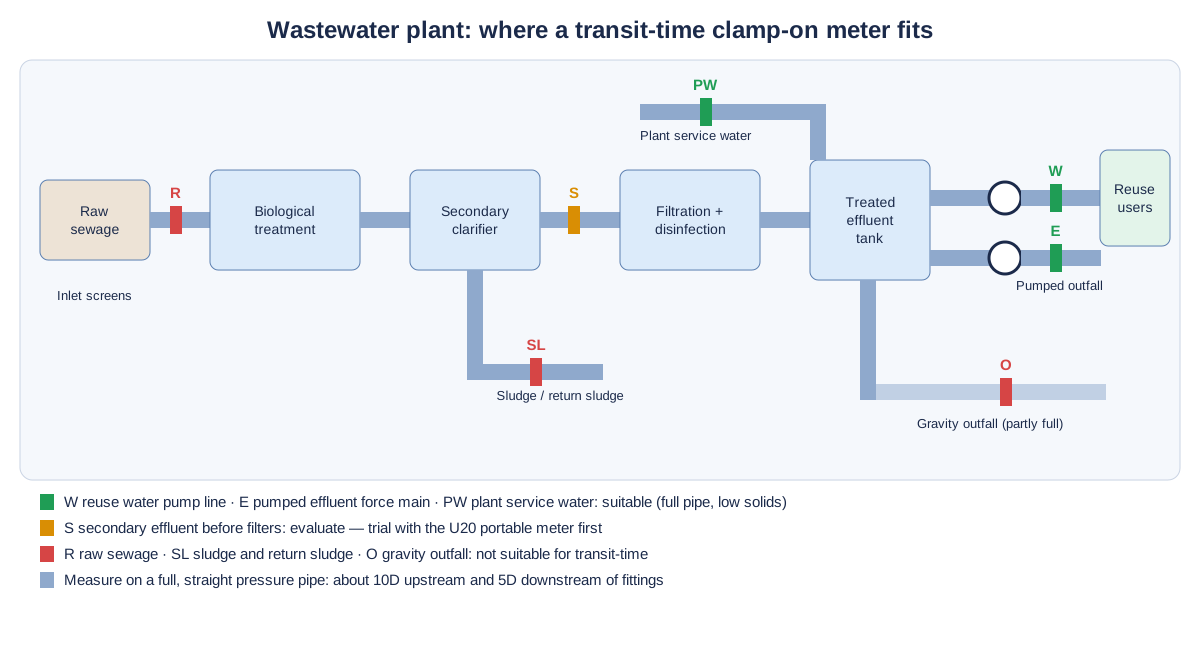
Typical Measuring Points for Treated Effluent and Reuse Water
The table lists the lines where treatment plants and reuse schemes most often ask for a clamp-on meter. Pipe sizes are typical values for orientation only; model data are from the SEGMENsensor product page and datasheets. We confirm the model from your pipe and water data.
| Measuring point | Typical pipe | Medium | Suggested model | Confirm before ordering |
|---|---|---|---|---|
| Pumped treated effluent / outfall force main | Steel, ductile iron or PE, DN200–DN1200 | Filtered or disinfected effluent, ambient | U11 (15–5000 mm, ±0.5%), Z-mode on large pipes | Pipe always full downstream of the pumps; lining; whether the regulator accepts the meter for reporting |
| Reuse water distribution pump discharge | Steel, ductile iron or PE, DN100–DN600 | Reclaimed water after filtration and disinfection | U10S / U10S PRO (±1%) or U11 where totals are allocated | Straight run after the pump and check valve; output to SCADA; reverse flow on standby pumps |
| Reuse water to a user (cooling tower make-up, process water, washdown) | PE, PVC or steel, DN50–DN300 | Reclaimed water, intermittent demand | U10 / U10S (±1%); U11 (from ±0.01 m/s) where flow is often low | Lowest flow; power at the branch (10–36 V DC; 90–245 V AC option); valve pit access |
| Plant service water (screen wash, dilution water, spray water) | Steel, PVC or PE, DN25–DN150 | Final effluent re-pumped inside the plant | U10S (from 15 mm) or U12 (DN15–DN65, ±2%) for indication | Outer diameter and wall; indication or totalising only |
| Membrane (UF / RO) feed, permeate and concentrate in advanced reuse | PVC-U, PE or stainless, DN25–DN300 | Filtered water, permeate, concentrate | U10S / U10S PRO; U12 or U13 on small skid pipes | Pipe material and wall on the skid; space for transducers between fittings |
| Secondary clarifier effluent before filters | Steel, PE or concrete channel | Low but variable suspended solids | Trial with the U20 portable meter first | Full pipe section available; signal quality over a day including peak flow and clarifier upsets |
| Checking an installed effluent meter (magnetic or other) | Any of the above, 25–1200 mm | Treated effluent | U20 portable (±1%, P2 sensors to +80 °C) | Straight run next to the installed meter; a period of steady flow; the installed meter's stated accuracy |
Installation Difficulties at Treatment Plants and How to Handle Them
Air after drops, weirs and filter backwash
Effluent often falls over weirs or into a contact tank before it is pumped, and filter backwash cycles send surges and air through the outlet line. Mount on the pump discharge, not on a suction line or below a free fall; on horizontal pipes place the transducers at the side (3 or 9 o'clock) and keep away from high points and air valves. The U11 rides through intermittent bubbles lasting up to 5 seconds; persistent air needs a better location.
Thick plastic pipe in reuse networks
Reuse distribution and plant service lines are frequently PE or PVC with thick walls. Enter the pipe material and the measured wall thickness, not the nominal one; a circumference tape gives the real outer diameter. Check signal strength and quality before relying on the reading (aim for a signal strength above 60% on the status screen), and on small, thick-walled pipes compare signal strength in V-mode and W-mode, because every extra pass through a thick plastic wall weakens the pulse.
Biofilm, scale and old linings
Reclaimed water lines grow biofilm, and older effluent mains carry scale or cement-mortar linings. Enter the lining type and thickness at set-up and recheck signal quality after the first months. Concrete pipes, concrete-lined steel and heavily encrusted mains do not give a reliable signal.
Dosing points and chemical mixing
Chlorine, bisulphite or coagulant injection just upstream leaves a poorly mixed zone. Measure upstream of the injection point, or far enough downstream for the dose to be mixed, and keep the usual straight run of about 10D upstream and 5D downstream of fittings. The full procedure is in the clamp-on flow meter installation guide and the installation video.
Valve pits, outdoor pipes and long cable runs
Reuse branches and outfall valves often sit in pits that flood. Transducers are IP68 and the U10-series transmitter is IP65 (enclosure codes per IEC 60529 — Degrees of protection provided by enclosures (IP Code)), so keep the transmitter above flood level; the sensor cable is 9 m as standard and up to 274 m on order. Follow your site's confined-space rules before entering a pit.
Send your effluent or reuse line data for a flow meter selection
Tell us the measuring point (outfall force main, reuse pump line, user branch, service water or membrane skid), pipe OD, wall thickness, material and lining, treatment stage of the water, flow range including low flow, available straight run, power, output to SCADA and quantity. OEM volume supply · samples 1–5 pcs in 5–7 working days · production lead time and MOQ confirmed with the quotation · quotation within 24 hours.
Can a Clamp-On Meter Be the Permit or Compliance Meter?
Only if your regulator accepts it for that point. Discharge permits name the measurement and its calibration, and the decision belongs to the permitting authority. The US EPA's NPDES Compliance Inspection Manual, Chapter 6 — Flow Measurement lists transit-time and Doppler meters among closed-pipe devices, expects closed-pipe meters to be calibrated at least once a year, and describes side-by-side checks with a portable meter. SEGMENsensor flow meters carry CE and UKCA marking; we do not claim any national approval for regulatory flow reporting.
In practice plants use clamp-on meters for three jobs around the compliance meter: internal metering of reuse water and service water, a second, independent reading on the effluent line, and periodic cross-checks of the installed meter with the U20. If the U20 is ±1% and the installed meter is stated at ±0.5%, readings averaged over the same steady period can differ by up to about ±1.5% while both are within specification (calculated value, worst case of the two accuracies added). A larger, repeatable difference is a reason to inspect the installed meter or send it for calibration; the clamp-on check does not replace that calibration.
How Do You Meter Reuse Water to Each User?
Put a fixed meter on each user branch and one on the distribution header, and compare the sum with the header total. Users such as cooling towers draw intermittently, so the branch meter must resolve low velocity: the U11 measures from ±0.01 m/s and the U10 series from ±0.03 m/s, in both directions. For scale, a DN100 branch at 1 m/s carries about 28.3 m³/h (calculated value from a 100 mm bore), and the same branch at 0.05 m/s carries about 1.4 m³/h. Totalizer values go to SCADA over RS485 Modbus, or as pulses to an existing RTU counter. If header and branch totals drift apart over weeks, look for an unmetered take-off, a leak or a meter whose signal quality has fallen because of biofilm.
Which Wastewater Lines Are Not Suitable?
Raw sewage, mixed liquor, all sludge lines and partly full or gravity pipes are not suitable for a transit-time clamp-on meter. Specifically:
- Raw sewage and inlet works: suspended solids, rags and grit scatter the ultrasonic pulse.
- Mixed liquor, return and waste activated sludge, primary and digested sludge: solids content far above what a transit-time meter can cross; see transit-time vs Doppler ultrasonic flow meters for why these are a different measuring problem.
- Partly full gravity outfalls, open channels and overflow pipes: the meter needs a full pipe; these are measured with open-channel methods.
- Air-entrained water just below weirs, free falls, backwash outlets and air valves.
- Concrete pipes, concrete-lined steel and heavily encrusted mains where the signal stays weak after the lining is entered.
- Biogas and other gases: SEGMENsensor clamp-on meters are for liquids only.
- Hazardous (Ex) areas, such as classified digester areas or inlet works: SEGMENsensor flow meters have no explosion-protected model.
Specifications That Matter for Effluent and Reuse Lines
The values below are taken from the SEGMENsensor ultrasonic flow meter product page and datasheets. Compare every model in the U10 to U20 model comparison.
| Parameter | U10 / U10S / U10S PRO | U11 | U20 portable |
|---|---|---|---|
| Pipe size | 25–1200 mm (U10) · 15–1200 mm (U10S, U10S PRO) | 15–5000 mm | 25–1200 mm |
| Accuracy · repeatability | ±1% · 0.2% | ±0.5% · 0.1% | ±1% |
| Flow velocity | ±0.03 to ±5 m/s | ±0.01 to ±12 m/s | ±0.01 to ±12 m/s |
| Liquid | Water; a small amount of bubbles allowed (U10) | Tolerates intermittent bubbles or impurities lasting up to 5 s | Clean liquids; not for slurries or heavy suspended solids |
| Power | 10–36 V DC; 90–245 V AC optional | 10–36 V DC or 90–245 V AC | Rechargeable 3000 mAh battery, about 16 hours per charge |
| Outputs · logging | Choose two: 4-20 mA, pulse (OCT), relay, RS232 / RS485 Modbus; HART optional · SD card up to 32 GB on the U10 series | SD card up to 32 GB, logging interval 1–99999 s | |
| Protection | Transmitter IP65, sensors IP68 | Sensors IP68 | P2 / P2H sensors IP68 |
| Certification | CE, UKCA (no explosion-protected model) | ||
Download the one-page datasheet (PDF)
Pipe size ranges, accuracy, transducer types and temperature ratings, outputs, power supply, enclosure ratings and ordering code for the SEGMENsensor clamp-on ultrasonic flow meter range. No registration required.
How Do You Trial a Doubtful Line Before Ordering?
Clamp the U20 portable clamp-on flow meter on the candidate section and log for at least a full day, including peak inflow and a filter backwash. Record signal strength and quality on the SD card alongside flow (logging interval 1–99999 s). If signal quality stays steady through the peaks, a fixed U10S or U11 will work at that point; if it collapses whenever solids or air rise, move the meter downstream to filtered water. This step matters most on secondary effluent, on old mains and on thick PE pipe. The U20 setup is shown in the U20 setup video.
Related Pages
For choosing a meter for clean water pipes in general, read the ultrasonic flow meter for water selection guide. Pump houses, DMA inlets and meter verification in drinking water networks are covered in clamp-on flow meters in water pump stations, and corrosive process liquids in the chemical plant guide. The output signal levels for SCADA follow IEC 60381-1 — analogue direct current signals for process control.
What Affects the Quotation?
We do not publish list prices because the configuration drives the quotation: fixed or portable, pipe size range and transducer type, accuracy class, outputs, power supply, cable length and quantity. Quotations are FOB China and exclude international freight and import duties or taxes; payment is 100% T/T in advance, and meters carry a 12-month warranty.
Get a clamp-on flow meter for treated effluent or reuse water
U11 for outfall force mains, U10 series for reuse pump lines and user branches, U20 for trials and meter checks. OEM volume supply · samples 1–5 pcs in 5–7 working days · production lead time and MOQ confirmed with the quotation · quotation within 24 hours. Download the clamp-on flow meter datasheet (PDF).
Frequently Asked Questions
Only treated wastewater. Filtered or disinfected effluent and reuse water in a full pressure pipe suit a transit-time clamp-on meter; raw sewage, mixed liquor and sludge contain too many solids for the ultrasonic pulse to cross the pipe.
Only if your regulator accepts it for that point. The permitting authority decides the measurement method and calibration. SEGMENsensor flow meters carry CE and UKCA marking and no national approval for regulatory flow reporting, so most plants use them for internal metering and cross-checks.
Yes, as a plausibility check. Log the U20 and the installed meter over the same steady period and compare the averages. With the U20 at ±1% and an installed meter at ±0.5%, differences up to about ±1.5% are within both specifications (calculated value); it does not replace a calibration.
Sometimes. Suspended solids in secondary effluent vary with load and clarifier performance, so trial the U20 portable meter for at least a day, including peak flow, before ordering a fixed meter. After filtration the signal is usually stable.
Yes. Enter the pipe material and the measured wall thickness at set-up and check signal strength and quality; on thick-walled plastic pipe compare V-mode and W-mode and use the mode with the stronger signal.
Samples of 1–5 pcs ship in 5–7 working days. Production lead time and MOQ are confirmed with the quotation, which we send within 24 hours on working days, FOB China.