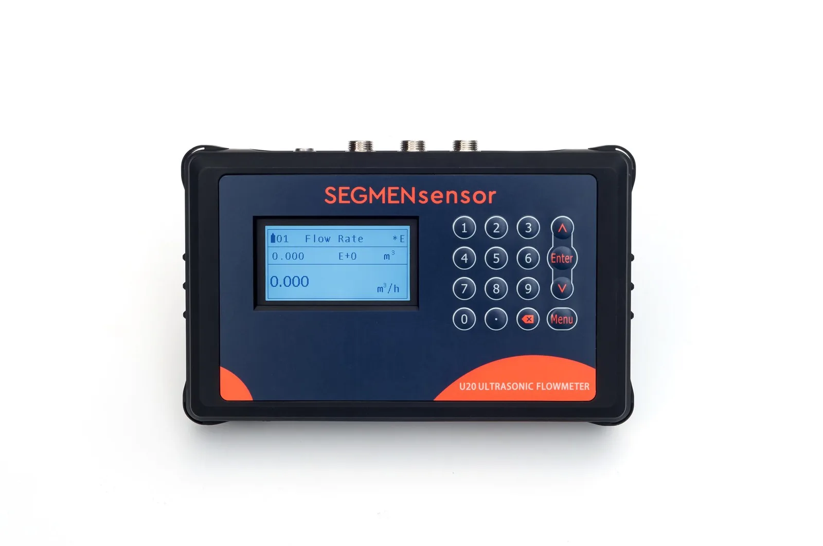
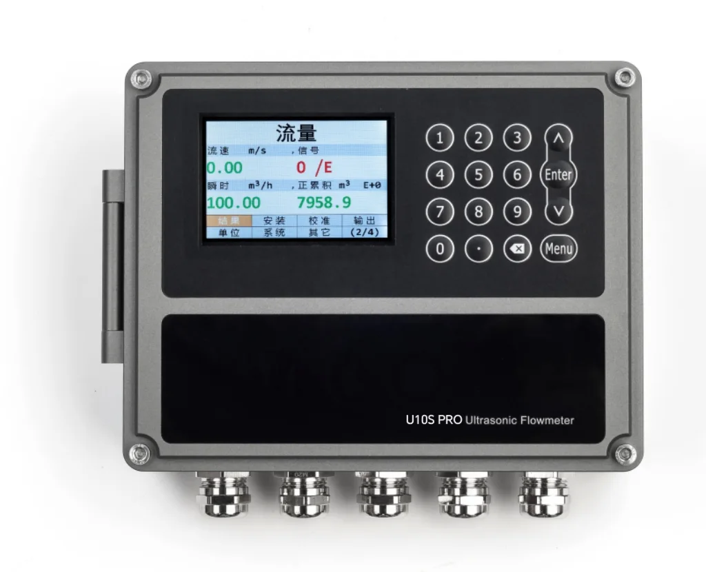
Put a fixed clamp-on meter on the pump station discharge header (U11, 15–5000 mm, ±0.5%) or on each pump's discharge line (U10S / U10S PRO, ±1%), and use the U20 portable meter to compare against an installed meter or to survey DMA inlets. Choose a full, straight section on the discharge side, enter the real pipe data, and judge a verification against the combined accuracy of both meters. Suction headers next to the pumps, partly full gravity mains and raw sewage are not suitable.
Why Use a Clamp-On Meter in a Pump Station?
Because a pump station cannot easily be drained to fit or remove a meter. A clamp-on ultrasonic flow meter straps two transducers to the outside of the pipe and times ultrasonic pulses sent with and against the flow; the transit-time difference gives velocity, and the pipe inner area gives volume flow. The method for liquids in closed conduits is described in ISO 12242 — Measurement of fluid flow in closed conduits: ultrasonic transit-time meters for liquid.
Pump stations ask three questions that a clamp-on meter answers without breaking the line. How much does each pump deliver? Most stations have one meter on the outlet main, so the share of each pump and its drift over the years stay unknown. Is the installed meter still right? Station meters feed water balance and non-revenue-water calculations, but removing one for a bench test takes the station offline. What flows into each district? DMA inlet chambers often have no meter, or an old one, and the minimum night flow is the first indicator of leakage. For choosing a meter for water pipes in general — pipe materials, accuracy classes and common mistakes — read our ultrasonic flow meter for water selection guide; this page covers the pump station and verification work only.
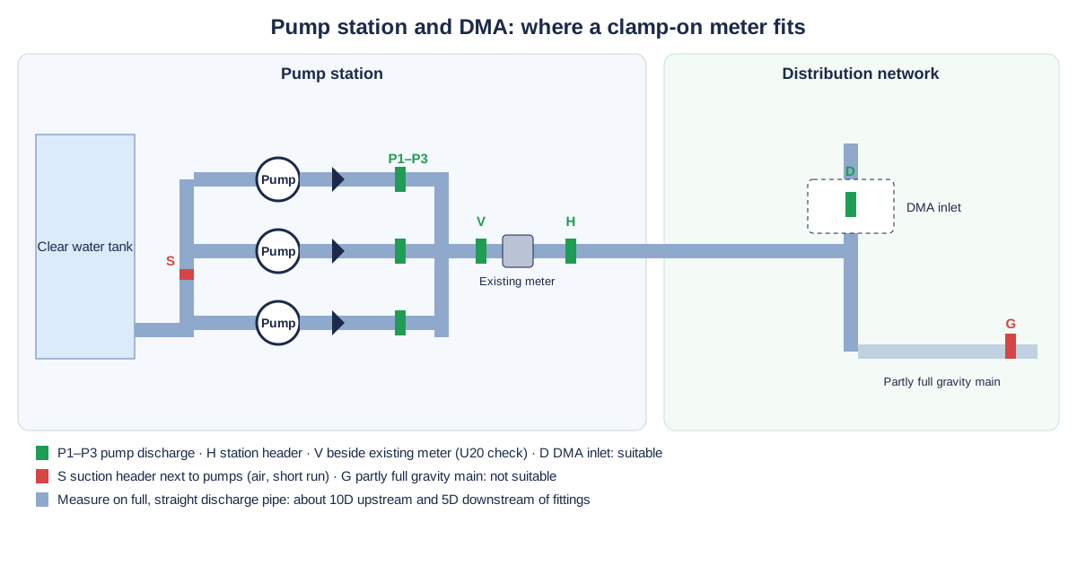
Typical Measuring Points in Pump Stations and Networks
The table lists the lines where water utilities and industrial pump houses most often ask for a clamp-on meter. Pipe sizes are typical values for orientation only; model data are from the SEGMENsensor product page and datasheets. We confirm the model from your pipe data.
| Measuring point | Typical pipe | Medium | Suggested model | Confirm before ordering |
|---|---|---|---|---|
| Station discharge header / outlet main | Steel or ductile iron, DN300–DN1200 | Treated or raw clean water, ambient | U11 (15–5000 mm, ±0.5%), Z-mode on large pipes | Longest straight run after the header; lining type and thickness; output to SCADA |
| Each pump discharge line | Steel or ductile iron, DN100–DN500 | Clean water | U10S / U10S PRO (±1%) fixed, or U20 for a pump test | Distance from check valve and isolation valve; whether reverse flow on standby pumps should be seen |
| Booster station inlet and outlet | Ductile iron, PE or PVC, DN80–DN400 | Potable water | U10 or U10S (±1%) | Power at the site (10–36 V DC; 90–245 V AC option); pipe material and SDR / wall |
| DMA inlet chamber | Ductile iron, PE or steel, DN50–DN300 | Potable water, low night flow | U11 (velocity from ±0.01 m/s) fixed; U20 for a survey | Lowest expected night flow; flow in both directions; chamber flooding and access |
| Reservoir or tank inlet / outlet | Steel or ductile iron, DN200–DN800 | Clean water; air possible on the outlet | U11 or U10S | Whether the outlet pipe stays full at low tank level |
| Checking an installed meter (magnetic or mechanical) | Any of the above, 25–1200 mm | Clean water | U20 portable (±1%, P2 to +80 °C, P2H to +130 °C) | Straight run next to the installed meter; a period of steady flow; the installed meter's stated accuracy |
| Seal water, wash-down and small service lines in the station | Steel, copper or plastic, DN15–DN65 | Clean water | U12 (DN15–DN65, ±2%) or U13 (DN15–DN40) for indication | Outer diameter; indication or totalizing only |
Installation Difficulties in Pump Stations and How to Handle Them
Short straight runs between pump, check valve and header
Pump houses are compact: pump, reducer, check valve and isolation valve sit within a few diameters. Aim for about 10D upstream and 5D downstream of fittings; where a pump line cannot give that, measure the whole station on the header and use the pump lines only for comparison between pumps. The full procedure is in the clamp-on flow meter installation guide and the installation video with chapters.
Swirl after pumps and out-of-plane bends
Two bends in different planes, or a pump volute close upstream, leave a swirling, uneven velocity profile. As a practical check, take readings with the transducer pair in two positions 90° apart around the pipe; if they differ noticeably, move further downstream or to the header. On large pipes use Z-mode with the transducers on opposite sides.
Air after start-up and at high points
Air drawn in by a suction vortex or trapped after a pump start scatters the signal. On horizontal pipes mount the transducers at the side (3 or 9 o'clock), never at the top, keep away from high points and air valves, and let the signal settle after each pump start before recording.
Cement-mortar lined ductile iron and old mains
Many water mains are ductile iron with a cement-mortar lining, or older pipe with tubercles inside. Enter the lining material and thickness at set-up, measure the wall and outer diameter (a circumference tape beats the nominal size), and check signal strength and quality before relying on the value. Concrete pipes and concrete-lined steel do not give a reliable signal.
Pump vibration, drives and flooded chambers
Fix the transducers with the chain fixtures and fresh couplant so vibration cannot move them, and run sensor cables away from variable-frequency drive and motor cables. Transducers are IP68 and the U10-series transmitter is IP65 (enclosure codes per IEC 60529 — Degrees of protection provided by enclosures (IP Code)), so in a DMA chamber that floods, keep the transmitter outside the chamber; the sensor cable is 9 m as standard and up to 274 m on order. Follow your site's confined-space rules before entering a chamber.
Send your pump station data for a flow meter selection
Tell us the measuring point (header, pump line, booster or DMA inlet), pipe OD, wall thickness, material and lining, the flow range including night flow, available straight run, power at the site, output to SCADA and quantity. OEM volume supply · samples 1–5 pcs in 5–7 working days · production lead time and MOQ confirmed with the quotation · quotation within 24 hours.
How Do You Check an Installed Flow Meter with a Clamp-On Meter?
Clamp the U20 portable clamp-on flow meter on a straight section next to the installed meter, record both over a period of steady flow, and compare the averages against the combined accuracy of the two meters. A practical sequence:
- Measure the real outer diameter and wall thickness at the U20 spot and enter pipe material, lining and liquid; a wrong diameter is a constant offset in every reading.
- Mount the transducers at the calculated spacing, check signal strength and quality, and confirm that the velocity is physically reasonable for the pump duty.
- Log both meters over the same period — at least several minutes of steady pumping, better a full pump cycle — using the U20 SD card (logging interval 1–99999 s).
- Compare the averaged flows or the totals over the same period, not single readings.
Size the expectation honestly. If the U20 is ±1% and the installed meter is stated at, for example, ±0.5%, the two readings can differ by up to about ±1.5% while both are within specification (calculated value, worst case of the two accuracies added). A difference inside that band means the installed meter reads plausibly; a larger, repeatable difference is a reason to inspect its installation, settings and electrodes or to send it for calibration. A clamp-on check does not replace a legal calibration for billing meters.
Can a Clamp-On Meter Measure DMA Night Flow?
Yes, if the pipe is full and the meter can resolve the low velocity. At night a DMA inlet often runs at a few centimetres per second. For example, a DN300 inlet at 0.05 m/s carries about 12.7 m³/h (calculated value from a 300 mm bore); the U11 measures from ±0.01 m/s, the U10 series from ±0.03 m/s. Where the chamber has a smaller-diameter section in the same line, measuring there raises the velocity and the signal. Because flow can reverse when a DMA has two feeds, choose a meter that measures in both directions and send flow and totalizer values to SCADA over RS485 Modbus. For a one-night survey, the U20 runs about 16 hours per charge; longer logging needs a fixed meter with power at the chamber.
Per-Pump Flow, Reverse Flow and Pump Curves
With one fixed meter on the header and the U20 moved from pump to pump, the station can see what each pump delivers at its actual duty point. Combined with suction and discharge pressure from a 4-20 mA pressure transmitter, that flow places each pump on its curve and shows wear before it shows in the energy bill. A clamp-on meter on a standby pump's discharge line also shows a negative flow if its check valve leaks and water runs back through the idle pump. The detailed energy-audit method for pumps is a separate topic; here the point is that every pump line becomes measurable without a shutdown.
Which Pump Station Lines Are Not Suitable?
Suction headers next to the pumps, partly full or gravity lines, concrete pipes, raw sewage and sludge, and hazardous (Ex) areas are not suitable. Specifically:
- Suction header close to the pumps: low pressure, vortex air and very short runs.
- Partly full gravity mains, overflow and open channels: the meter needs a full pipe.
- Concrete pipes, concrete-lined steel and heavily tuberculated old pipes where the signal stays weak after the lining is entered.
- Raw sewage, sludge and stormwater with heavy solids: suspended solids scatter the signal; see transit-time vs Doppler ultrasonic flow meters. Filtered effluent and reuse water are covered in clamp-on flow meters for treated effluent and reuse water.
- Air-entrained water just after a pump start or below air valves and high points.
- Hazardous (Ex) areas, such as classified sewage wet wells: SEGMENsensor flow meters have no explosion-protected model.
Specifications That Matter in Pump Stations
The values below are taken from the SEGMENsensor ultrasonic flow meter product page and datasheets. Compare every model in the U10 to U20 model comparison.
| Parameter | U10 / U10S / U10S PRO | U11 | U20 portable |
|---|---|---|---|
| Pipe size | 25–1200 mm (U10) · 15–1200 mm (U10S, U10S PRO) | 15–5000 mm | 25–1200 mm |
| Accuracy · repeatability | ±1% · 0.2% | ±0.5% · 0.1% | ±1% |
| Flow velocity | ±0.03 to ±5 m/s | ±0.01 to ±12 m/s | ±0.01 to ±12 m/s |
| Power | 10–36 V DC; 90–245 V AC optional | 10–36 V DC or 90–245 V AC | Rechargeable 3000 mAh battery, about 16 hours per charge |
| Outputs · logging | Choose two: 4-20 mA, pulse (OCT), relay, RS232 / RS485 Modbus; HART optional · SD card up to 32 GB on the U10 series | SD card up to 32 GB, logging interval 1–99999 s | |
| Protection | Transmitter IP65, sensors IP68 | Sensors IP68 | P2 / P2H sensors IP68 |
| Certification | CE, UKCA (no explosion-protected model) | ||
Download the one-page datasheet (PDF)
Pipe size ranges, accuracy, transducer types and temperature ratings, outputs, power supply, enclosure ratings and ordering code for the SEGMENsensor clamp-on ultrasonic flow meter range. No registration required.
How Do You Connect the Meter to SCADA or Telemetry?
Use 4-20 mA for the flow value and RS485 Modbus for flow, totalizer and diagnostics. On the U10 series and U11 you choose two outputs from 4-20 mA (signal levels per IEC 60381-1 — analogue direct current signals for process control), pulse (OCT), relay and RS232 / RS485 Modbus, with HART as an option. A pulse output feeds an existing RTU counter at a DMA chamber; a relay gives a low-flow or no-flow alarm on a pump line. For the same logic on large plant utilities, see our power plant cooling water guide and the steel mill cooling water guide. The measuring principle in one minute is in the transit-time video.
What Affects the Quotation?
We do not publish list prices because the configuration drives the quotation: fixed or portable, pipe size range and transducer type, accuracy class, outputs, power supply, cable length and quantity. Quotations are FOB China and exclude international freight and import duties or taxes; payment is 100% T/T in advance, and meters carry a 12-month warranty.
Get a clamp-on flow meter for your pump station
U11 for station headers and DMA inlets, U10 series for pump lines and booster stations, U20 for pump tests and meter checks. OEM volume supply · samples 1–5 pcs in 5–7 working days · production lead time and MOQ confirmed with the quotation · quotation within 24 hours. Download the clamp-on flow meter datasheet (PDF).
Frequently Asked Questions
Yes, as a plausibility check. Clamp the U20 on a straight section next to the installed meter, log both over a period of steady flow and compare the averages. With the U20 at ±1% and an installed meter at ±0.5%, differences up to about ±1.5% are within both specifications (calculated value); it does not replace a legal calibration.
On the discharge side. The suction header next to the pumps has low pressure, vortex air and very short straight runs; a full, straight section of the discharge line or header, about 10D upstream and 5D downstream of fittings, gives a stable signal.
Yes, on a full pipe. The U11 measures from ±0.01 m/s and the U10 series from ±0.03 m/s, in both directions. A DN300 inlet at 0.05 m/s carries about 12.7 m³/h (calculated value), so measure on the smallest suitable pipe section to raise the velocity.
Usually, if the lining is entered at set-up and the signal strength and quality are good. Concrete pipes, concrete-lined steel and heavily tuberculated old mains do not give a reliable signal.
Yes. SEGMENsensor clamp-on meters measure flow in both directions, so a leaking check valve on an idle pump shows as a negative flow on that pump's discharge line.
Samples of 1–5 pcs ship in 5–7 working days. Production lead time and MOQ are confirmed with the quotation, which we send within 24 hours on working days, FOB China.