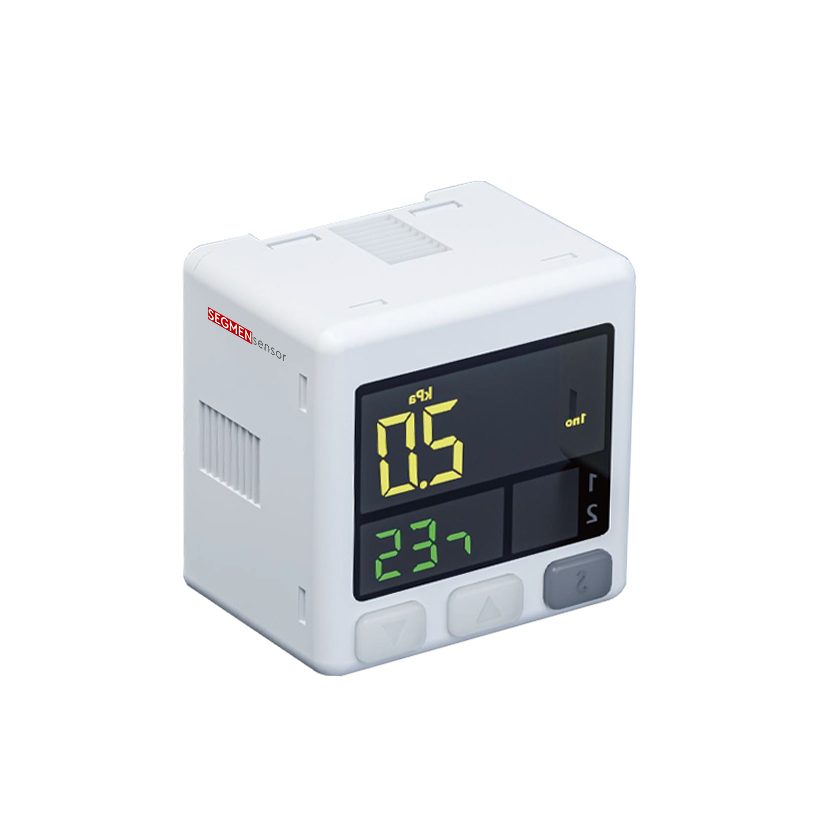
For HVAC water circuits, choose a 2-wire 4-20 mA pressure transmitter whose full scale sits about 25–65% above normal operating pressure, so working pressure lands at 60–80% of span. Chilled-water and heating loops usually need 0–10 bar or 0–16 bar, 316L wetted parts and IP67. Use two transmitters across the remote coil for differential-pressure pump control.
This guide is for chiller, heat-pump, air-handling-unit and pump-skid OEMs, and for the controls integrators who specify sensors for building management systems (BMS / BAS). It explains where pressure transmitters sit in an HVAC plant, how to pick range, output and connection, and which limits to check before you release a drawing. Product details are on the 4-20 mA pressure transmitter and pressure sensors and switches pages.
What Does a Pressure Transmitter Do in an HVAC System?
It gives the controller a live pressure value. Where a mechanical gauge only shows pressure to a person standing next to it, a transmitter sends a 4-20 mA signal (4 mA = zero of the range, 20 mA = full scale) to the BMS, the chiller controller or the pump drive (how this differs from a voltage-output device is explained in pressure transducer vs transmitter). The controller then uses it for four jobs:
- Pump speed control: holding a differential-pressure set point across the most remote coil, so a variable-speed pump slows down when valves close.
- System fill and leak monitoring: watching static pressure at the expansion tank; a slow fall indicates a leak or a failed make-up valve.
- Equipment protection: low suction pressure or high discharge pressure alarms on pumps, and inlet / outlet pressure across chiller and heat-pump heat exchangers.
- Energy and fault diagnostics: trending pump differential pressure together with flow to spot clogged strainers, air in the system or a pump running off its curve.
Where Are Pressure Transmitters Installed in a Chilled-Water Loop?
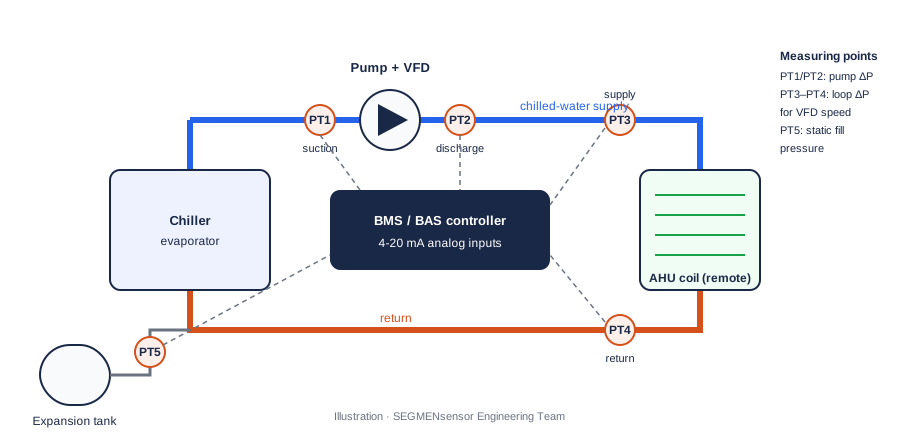
Five measuring points cover most hydronic plants. The illustration below shows a typical variable-primary chilled-water loop; heating-water loops use the same logic.
| Point | What it measures | Used for | Typical range choice* |
|---|---|---|---|
| PT1 – pump suction | Inlet pressure of the circulating pump | Low-pressure / cavitation alarm, pump ΔP with PT2 | 0–6 or 0–10 bar |
| PT2 – pump discharge | Outlet pressure of the pump | Pump ΔP, high-pressure alarm | 0–10 or 0–16 bar |
| PT3 / PT4 – remote coil supply and return | Pressure on each side of the most remote coil or branch | Loop differential pressure for VFD pump speed control | Two identical ranges, e.g. 0–10 bar |
| PT5 – expansion tank line | Static fill pressure of the closed loop | Leak detection, make-up water control | 0–4 or 0–6 bar |
| Heat exchanger in / out | Pressure drop across chiller evaporator, condenser or plate heat exchanger | Fouling and low-flow alarm | Match the loop range |
*Typical choices for buildings where the loop is rated around 10–16 bar. Always size the range from your own design and test pressure (see the selection steps below); all values are standard SEGMENsensor ranges.
How Do You Choose an HVAC Pressure Transmitter? (Selection Steps)
- Size the range. Pick a full scale where normal operating pressure sits at 60–80% of span. A loop that runs at 6 bar fits a 0–10 bar transmitter; a high-rise riser at 11 bar fits 0–16 bar. Make sure the system test pressure stays within the overload limit; burst pressure is 3× full scale on standard ranges.
- Decide gauge or differential. HVAC water loops are measured as gauge pressure. For loop or filter differential pressure, either use two gauge transmitters and subtract in the controller, or specify a differential instrument; see gauge vs absolute vs differential pressure transmitters.
- Check medium and temperature. 316L stainless steel wetted parts suit chilled water, heating water and glycol mixtures. Rated media temperature is -20 °C to +85 °C; for heating water above +85 °C or steam, a cooling element or siphon is fitted and the arrangement is confirmed per project.
- Match the output to the controller. 4-20 mA 2-wire is the default for BMS analog inputs and tolerates long cable runs; RS485 / Modbus RTU is available on request for digital integration. Wiring details are in the 4-20 mA pressure transmitter wiring guide.
- Choose the connection. G1/4" male is standard, with G1/2", 1/4" NPT and 1/2" NPT available, so you can match BSPP fittings for Europe and Australia or NPT for North America. Electrical connection is an M12×1 4-pin connector, a Hirschmann (DIN) plug or a flying lead.
- Protect against water hammer and condensation. Fast-closing valves can create pressure spikes; fit a snubber on pump discharge points (pressure snubbers and water hammer). On chilled-water pipes below the dew point, choose IP67 or the optional IP68 and route the cable with a drip loop. IP codes are defined in IEC 60529 ↗.
Can the Same Transmitter Be Used on Air Ducts or Refrigerant Lines?
Not automatically. SEGMENsensor transmitters start at a 0–0.1 bar (10 kPa) span, which covers low-pressure water and compressed air but is coarser than the few-hundred-pascal readings typical of duct static pressure and filter monitoring; those points normally use a dedicated low-differential-pressure instrument. On the refrigerant side, range, connection, sealing material and media compatibility depend on the refrigerant and the compressor design, so they are confirmed per project. For high- and low-pressure cut-out duty on compressors, see our OEM pressure switches with custom trip points.
Specifying transmitters for a chiller, heat pump or pump skid?
Send the medium, operating and test pressure, temperature, process thread, connector and annual volume. We recommend the range and build and return a written quotation within 24 hours on working days.
SEGMENsensor Pressure Transmitter Specifications for HVAC
All figures below are taken from the 4-20 mA pressure transmitter product page. Unit conversions are calculated values.
| Parameter | Specification |
|---|---|
| Measurement range | 0–0.1 bar to 0–400 bar, specified at order (0.1 bar = 10 kPa ≈ 1.45 psi; 16 bar ≈ 232 psi, calculated) |
| Ranges for HVAC water circuits (ceramic PT-C) | 0.1 / 0.25 / 0.6 / 1 / 2.5 / 4 / 6 / 10 / 16 / 25 / 40 bar |
| Sensing principle | Ceramic capacitive or piezoresistive |
| Accuracy | ±0.25% FS standard; ±0.1% FS high-accuracy version |
| Output | 4-20 mA, 2-wire loop-powered; RS485 / Modbus RTU on request |
| Supply voltage | 12–36 V DC; max loop resistance 600 Ω at 24 V |
| Wetted materials | 316L stainless steel diaphragm and housing |
| Process connection | G1/4" male standard; G1/2", 1/4" NPT, 1/2" NPT |
| Electrical connection | M12×1 4-pin, Hirschmann (DIN) plug or flying lead |
| Temperature | Media -20 °C to +85 °C; ambient -40 °C to +85 °C; compensated 0 °C to +60 °C |
| Protection | IP67 standard; IP68 optional |
| Burst pressure / stability | 3× full scale (standard ranges) / ±0.1% FS per year |
| Certifications | CE, RoHS 3; ISO 9001:2015 quality system |
| Samples and lead time | Qualification samples 1–5 pcs in 5–7 working days; production lead time and MOQ confirmed with the quotation |
Download the one-page datasheet (PDF)
Ranges, accuracy classes, outputs, supply voltage, process connections, materials, temperature limits, IP rating, dimensions and the ordering code for SEGMENsensor pressure transmitters.
More documents: pressure sensor downloads
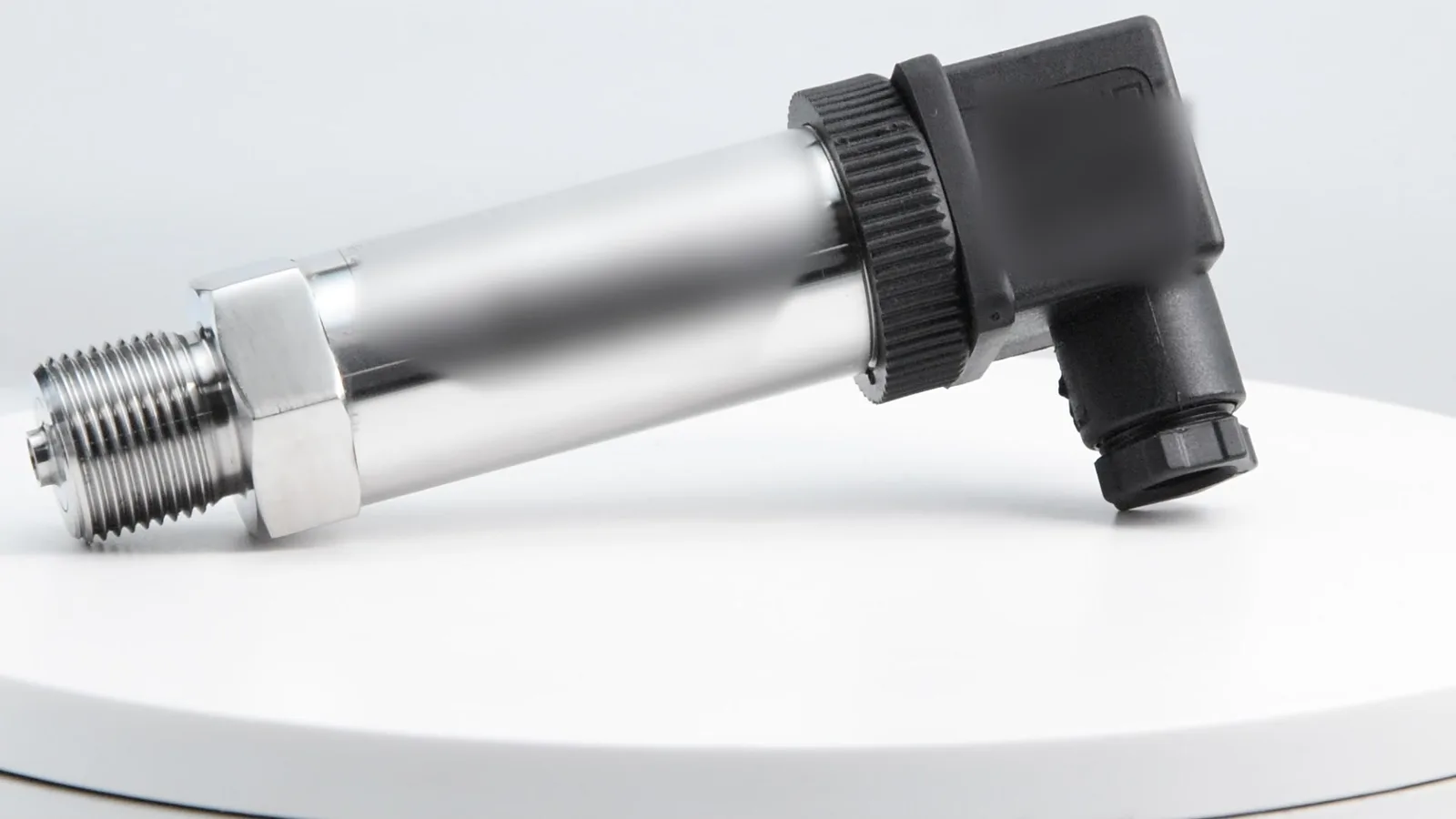
Worked Example: Sizing a Transmitter for Pump Speed Control
A chilled-water loop has a design working pressure of 6 bar at the pump discharge and a test pressure of 9 bar. The controls engineer wants a 0.5 bar differential-pressure set point across the remote coil.
Deciding between a local dial and a signal to the BMS for that differential point? Read differential pressure gauge vs transmitter.
- Range: 6 bar ÷ 0.7 ≈ 8.6 bar, so the next standard range is 0–10 bar (6 bar = 60% of span). The 9 bar test pressure stays inside the span.
- Signal: at 0–10 bar, each bar is 1.6 mA, so 6 bar reads 4 + 6 × 1.6 = 13.6 mA (calculated). You can check other values with the 4-20 mA calculator.
- Differential set point: with two ±0.25% FS transmitters on 0–10 bar, each may deviate by up to ±0.025 bar, so the difference can deviate by up to ±0.05 bar, about 10% of a 0.5 bar set point (calculated worst case). If tighter control is needed, choose the ±0.1% FS version (±0.02 bar worst case) or a differential instrument. See accuracy: % of full scale vs % of reading.
Factory Supply for HVAC Equipment OEMs
Segmen Industrial Development Co., Ltd. (SEGMENsensor) was founded in Shenzhen in 2019, with an engineering team that has 20+ years of sensor experience, and supplies 200+ OEM customers in 30+ countries. For HVAC builders we adapt range, process thread, connector, cable length and private labelling to the equipment, and every transmitter is tested before shipment. Quotations are FOB China with 100% T/T before shipment and a 12-month warranty. For data-center cooling loops, pressure is often measured together with flow; see data center cooling water flow monitoring.
FAQ
General questions
Most building chilled-water and heating loops use 0–10 bar or 0–16 bar. Choose the range so normal operating pressure is 60–80% of full scale and the test pressure does not exceed the span; SEGMENsensor offers standard ranges from 0–0.1 bar to 0–400 bar.
Install one transmitter on the supply and one on the return at the most remote coil, wire both 4-20 mA signals to the BMS and let the controller subtract them. Use identical ranges, and choose the ±0.1% FS version when the set point is small compared with the range.
Yes for glycol mixtures and heating water up to +85 °C, which is the rated media temperature of the 316L transmitter. Above +85 °C a cooling element or siphon is fitted, and the arrangement is confirmed per project.
4-20 mA is the simplest choice for BMS analog inputs: it is 2-wire, tolerates up to 600 Ω loop resistance at 24 V and shows a wiring fault when the current drops below 4 mA. RS485 / Modbus RTU is available on request when many points share one bus.
Procurement Q&A
Send the medium, operating and test pressure, media temperature, required range and output, process thread, electrical connector, cable length and annual volume. Engineers reply within 24 hours on working days; quotations are FOB China.
Qualification samples of 1–5 pcs ship in 5–7 working days. Production lead time and MOQ are confirmed with the quotation.
References
- IEC 60381-1 — Analogue signals for process control systems: direct current signals ↗
- IEC 60770-1 — Transmitters for use in industrial-process control systems: methods for performance evaluation ↗
- IEC 60529 — Degrees of protection provided by enclosures (IP code) ↗
Related reading: 4-20 mA pressure transmitters · 4-20 mA pressure transmitter wiring · Gauge vs absolute vs differential · Data center cooling water flow monitoring
Last updated: 7 November 2026. Specifications reflect SEGMENsensor product pages and datasheets at the time of writing; combinations of range, output, connection and temperature are confirmed per project.