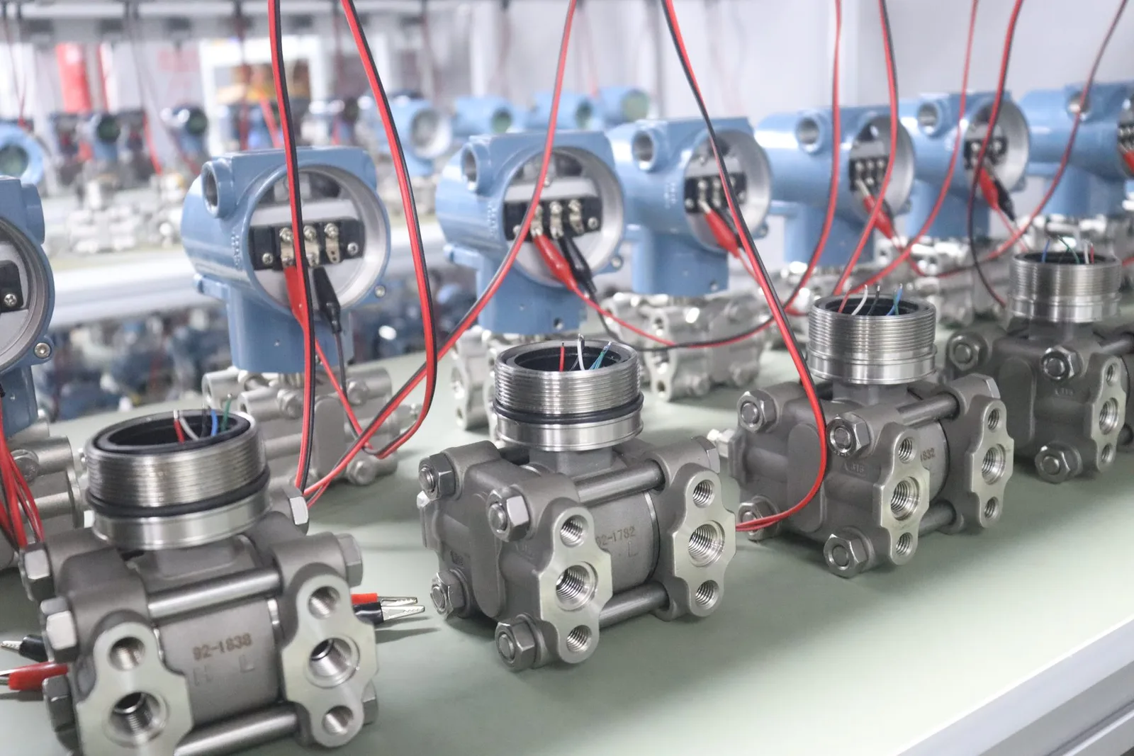
Use a differential pressure gauge when someone walks past the equipment and only needs to see the pressure drop — a filter, strainer or coil checked on a maintenance round. Use a differential pressure transmitter when the ΔP value must reach a PLC, BMS or data logger: remote alarms, filter-change prediction, fan or pump control, flow calculation across an orifice, or level in a pressurised tank. Many plants keep the gauge for local reading and add a transmitter for the control system.
What is a differential pressure gauge?
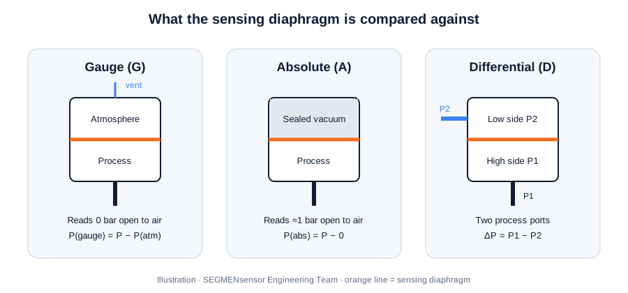
A differential pressure gauge is a local indicator with two process connections, high side (P1) and low side (P2). The difference between the two pressures deflects a diaphragm, bellows or magnetically coupled piston, and a mechanism turns that movement into a pointer position on a dial. Because the energy comes from the process itself, a mechanical gauge needs no power supply and no wiring.
Some gauges add one or two adjustable switch contacts so that a high ΔP can trip an alarm lamp or relay. That turns the gauge into a simple on/off device, similar to a pressure switch: it tells you that a limit was crossed, but not the actual value over time. The reading stays on the dial and only exists when someone looks at it.
What is a differential pressure transmitter?
A differential pressure transmitter has the same two ports, but the pressure difference acts on an electronic sensing element — in a piezoresistive design, a diaphragm carrying a Wheatstone bridge. The electronics linearise and temperature-compensate the bridge signal and convert it into a standard output: a 2-wire 4–20 mA loop as described in IEC 60381-1, a 0–10 V voltage signal or an RS485 digital value.
The output goes to a PLC, DCS, building management system or recorder, so the ΔP can be logged, trended, compared with several alarm limits in software and used directly in a control loop. Performance of process transmitters of this kind is evaluated with the methods in IEC 60770-1. The reference concept (two process ports instead of atmosphere or vacuum) is explained in our gauge vs absolute vs differential pressure transmitter guide.
How are the two installed on the same filter?
Differential pressure gauge vs transmitter: decision table
| Criterion | Differential pressure gauge | Differential pressure transmitter |
|---|---|---|
| Indication | Pointer on a local dial | Electrical signal; local display optional |
| Output | None, or on/off switch contacts on alarm versions | 4–20 mA (2-wire), 0–10 V or RS485 |
| Power | None for mechanical gauges | 12–36 V DC loop supply (SEGMENsensor 4–20 mA units) |
| Remote reading | No — someone must look at the dial | Yes — PLC, DCS, BMS or data logger |
| Alarms | Fixed contact set points, if fitted | Any number of limits in software, with time delay and logging |
| Trend data | Manual readings on a log sheet | Continuous, time-stamped values |
| Accuracy statement | As stated by the gauge maker on the dial or datasheet | ±0.25% FS or ±0.1% FS (SEGMENsensor) |
| Fault detection | A stuck pointer can look like a normal reading | Live-zero 4 mA: a broken loop reads near 0 mA |
| Typical uses | Filter and strainer checks on rounds, local coil and fan readings | Filter-change alarms, fan and pump control, orifice flow, pressurised-tank level |
When should you replace a DP gauge with a transmitter?
Replace or supplement the gauge with a transmitter if one or more of the following applies:
- Nobody reads the dial often enough. A filter that clogs between maintenance rounds needs a remote alarm, not a pointer.
- You want to change filters on condition, not on calendar. A ΔP trend shows how fast the element loads, so replacement can be planned.
- The value drives control. Fan speed on duct or filter ΔP, pump speed on differential head, or damper position all need a continuous signal.
- You calculate flow or level from ΔP. Flow across an orifice or venturi follows the square root of ΔP; level in a pressurised tank equals ΔP divided by liquid density and gravity. Both need a signal the PLC can compute with.
- Records are required. Energy audits, cleanroom and HVAC commissioning, or quality systems ask for logged values rather than handwritten readings.
Keep the gauge — or a transmitter with a local display — where operators need a reading at the equipment, for example during start-up or when the control system is offline.
How do you size and read a DP transmitter? A worked example
A cartridge filter on a cooling-water line runs at about 6 bar line pressure. The clean element drops roughly 80 mbar, and maintenance wants an alarm at 300 mbar (example values for illustration).
- Choose the ΔP span above the alarm point: 0–500 mbar (0–0.5 bar) leaves headroom above 300 mbar for a dirty or blocked element.
- Check static pressure: both ports sit at about 6 bar, so the static (line) pressure rating must exceed 6 bar with margin — state this separately from the ΔP range when you order.
- Convert the signal: ΔP = (I − 4 mA) / 16 mA × 500 mbar. At 300 mbar the output is 4 + 16 × 300/500 = 13.6 mA (calculated).
- Check resolution against accuracy: ±0.25% FS on a 500 mbar span is ±1.25 mbar (calculated) — far finer than the 80 to 300 mbar change you are watching.
- Set alarms in the PLC: for example a warning at 250 mbar and a change-filter alarm at 300 mbar, with a time delay to ignore short surges.
Convert bar, mbar, kPa, psi or inH₂O with the pressure unit converter, and check mA values with the 4–20 mA calculator. Unit definitions follow the NIST SI units reference (1 bar = 100 kPa).
SEGMENsensor pressure transmitter specifications for differential duty
| Parameter | Value |
|---|---|
| Pressure reference | Gauge, absolute or differential |
| Ranges | 0–0.1 bar to 0–400 bar; differential ΔP range and static pressure confirmed per project |
| Accuracy | ±0.25% FS standard; ±0.1% FS high-accuracy version |
| Output | 4–20 mA 2-wire, 0–10 V or RS485 |
| Supply / loop | 12–36 V DC; max. 600 Ω loop resistance at 24 V |
| Temperature | Media -20 °C to +85 °C; ambient -40 °C to +85 °C; compensated 0 °C to +60 °C |
| Protection | IP67 standard; IP68 optional |
| Process connections | G1/4, G1/2, 1/4 NPT, 1/2 NPT or flush diaphragm |
| Wetted materials | 316L stainless steel; Hastelloy or ceramic on request |
| Certifications | CE, RoHS 3; ATEX / IECEx options; quality system ISO 9001:2015 |
| Samples / production | From 1 pc for qualification (1–5 pcs in 5–7 working days); production lead time and MOQ confirmed with the quotation |
Download the one-page datasheet (PDF)
Ranges, accuracy classes, outputs, process and electrical connections, wetted materials and ordering information for SEGMENsensor pressure transmitters. No registration required.
See ranges and connections on the 4–20 mA pressure transmitter product page, or the full pressure sensor range.
Send the ΔP range, static line pressure, medium and output. An application engineer replies within 24 hours with a recommended configuration. Request an engineering review → · Qualification samples 1–5 pcs in 5–7 working days.
Where is each one typically used?
HVAC and data-centre cooling. Air-handling units use ΔP across filters and coils; chilled-water loops use differential head across pumps and heat exchangers. A gauge serves the technician on site, while a transmitter feeds the BMS for pump speed control. SEGMENsensor transmitters start at a 0–0.1 bar (10 kPa) span, which suits water-side ΔP across pumps, coils, heat exchangers and strainers; air-side filter readings of a few hundred pascals are below that span, so confirm them with us per project. See our HVAC pressure transmitter guide for measuring points in a chilled-water loop.
Water and process filtration. Strainers and cartridge filters on cooling water, boiler feed and treated-water lines are classic ΔP points. Where filters are remote or critical, the transmitter's alarm and trend replace routine walk-downs.
Hydraulic and lubrication systems. Return and pressure filters on hydraulic power units are monitored for clogging; a transmitter lets the machine controller warn before the bypass valve opens.
Flow and level. Across an orifice plate or venturi, ΔP gives flow; between the bottom and the gas space of a closed tank, ΔP gives level. Both are transmitter applications, because the PLC must compute the result. All applications are typical uses, evaluated per project.
How do you specify a differential pressure transmitter?
- ΔP range — normal and maximum difference, in bar, mbar, kPa or psi.
- Static (line) pressure — the highest pressure on either port.
- Medium and temperature — water, oil, air or other; media -20 °C to +85 °C as standard.
- Output and supply — 4–20 mA, 0–10 V or RS485; 12–36 V DC.
- Connections — process thread (G1/4, G1/2, 1/4 NPT, 1/2 NPT) and electrical connector or cable.
- Environment and approvals — IP67 or IP68; ATEX / IECEx where required.
- Quantity — evaluation samples and estimated annual volume.
For a wider checklist covering gauge and absolute units too, read the 4–20 mA pressure transmitter selection guide.
Frequently Asked Questions
A differential pressure gauge shows the pressure difference between two ports on a local dial and needs no power. A differential pressure transmitter measures the same difference electronically and sends it as a 4–20 mA, 0–10 V or RS485 signal to a PLC, BMS or recorder, so the value can be logged, trended and alarmed remotely.
Yes, in most cases. The transmitter connects to the same high (P1) and low (P2) process lines and covers the same ΔP range. If operators still need a local reading, choose a transmitter with a display or keep the gauge in parallel on a separate valve manifold.
A mechanical differential pressure gauge does not need power: the pressure difference moves a diaphragm, piston or magnet that drives the pointer. Only gauges with built-in electrical switch contacts need wiring for the alarm circuit. A differential pressure transmitter always needs a supply, for example 12–36 V DC loop power for a 2-wire 4–20 mA unit.
For a linear 4–20 mA unit, ΔP = (I − 4 mA) / 16 mA × span. On a 0–500 mbar transmitter, 12 mA means 250 mbar and 20 mA means the full 500 mbar. A reading near 0 mA indicates a broken loop rather than zero differential pressure.
The static (line) pressure rating must exceed the highest pressure either port can see, not just the ΔP range. A filter on a 10 bar water line can show a 0.3 bar drop, but both ports still sit at about 10 bar, so the instrument body and sensor must be rated for the line pressure plus a safety margin.
Send the ΔP range, the maximum static line pressure, the medium and its temperature, the output signal (4–20 mA, 0–10 V or RS485), the process and electrical connections, any approvals required, and your annual quantity. An application engineer replies with a recommended configuration and quotation within 24 hours on working days.
Qualification samples of 1–5 pcs ship in 5–7 working days. Production lead time and MOQ are confirmed with the quotation. Quotations are FOB China with 100% T/T in advance, and products carry a 12-month warranty.
SEGMENsensor pressure transmitters are available in gauge, absolute and differential configurations across ranges from 0–0.1 bar to 0–400 bar, with ±0.25% FS standard accuracy or ±0.1% FS high accuracy. The exact ΔP range and static pressure rating of a differential unit are confirmed per project.
Last updated: · SEGMENsensor Engineering Team