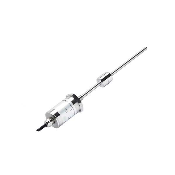
If the tank or basin is up to 8 m deep, has a top opening for a rod or cable and the float can move freely, a magnetostrictive level sensor gives water level without any vent tube, without barometric correction and without density scaling. If the measuring point is a deep well, borehole or narrow pipe, or the probe must hang from a cable deeper than 8 m, keep a vented submersible sensor (0–200 mWC) and protect the vent end — or use an absolute sensor with a separate barometric reference.
Why does a submersible level sensor need a vent tube?
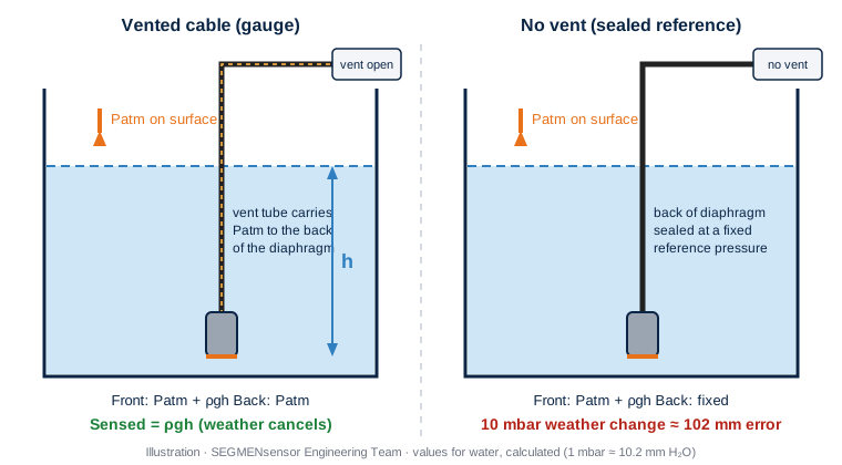
A submersible (hydrostatic) level sensor sits at the bottom of the tank and measures the pressure of the liquid column above it: pressure = density × gravity × height. But the surface of an open tank is also pushed down by the atmosphere, so the diaphragm actually sees liquid pressure + air pressure. The thin vent tube inside the cable connects the back of the diaphragm to the same atmosphere, so the air pressure cancels and only the liquid column remains. This principle is explained in detail in our article on why a submersible level sensor needs a vent tube.
The vent tube works well — until it does not. A pinched cable gland, a cable end sealed into a wet junction box, condensation that runs down the tube, or a flooded pit can block or wet the vent. Then the reading starts to follow the weather. Water has a density of about 1000 kg/m³, so 1 mbar of air pressure equals about 10.2 mm of water column (calculated). A 10 mbar change in barometric pressure therefore appears as roughly 102 mm of level change on a sensor without a working vent (calculated value).
How does a magnetostrictive level sensor measure water level without a vent?
A magnetostrictive level sensor does not measure pressure at all. It measures where the float is:
- The float follows the surface. A float with a ring magnet rides on the liquid and slides along a stainless steel rod (or a flexible cable on SE-LX30).
- A current pulse travels down the waveguide. The electronics in the head send a short pulse along a magnetostrictive wire inside the rod; where its field meets the float magnet, a torsional strain wave is created.
- Time of flight gives position. The strain wave travels back to the head at a known speed; the time between pulse and return is converted into an absolute level signal (4–20 mA, 0–10 V, 0–5 V or RS485).
Because the result is a position along the rod, air pressure above the liquid has no influence, and there is nothing to vent. A density change does not move the reading the way it does on a pressure sensor either; it only changes how deep the float sits in the liquid, which is a small, fixed offset that can be zeroed at commissioning. Read the full principle in how a magnetostrictive level transmitter works, or watch how a magnetostrictive sensor works.
Vented submersible vs magnetostrictive: the two principles side by side
Magnetostrictive vs vented submersible: comparison table
| Criterion | Vented submersible (hydrostatic) | Magnetostrictive (float on rod) |
|---|---|---|
| What is measured | Pressure of the liquid column | Position of the float along the rod |
| Vent tube / barometric correction | Needed (vented cable) — or separate barometric correction with a sealed sensor | Not needed |
| Effect of liquid density | Reading scales with specific gravity; must be set in the PLC | Level reading not scaled by density; small float-immersion offset zeroed at start-up |
| SEGMENsensor range | 0–0.5 to 0–200 mWC | 25–8000 mm (SGM-LS10); 200–8000 mm (SE-LX10 / LX20 / LX30) |
| Accuracy figures | ±0.1% FS standard; ±0.05% FS high-accuracy version | SE-LX non-linearity ±1 mm; SGM-LS10 repeatability ±0.005 mm |
| Mounting | Probe hangs on its cable from the top; works through a narrow bore | Rod or flexible cable from a top flange or thread; float must fit the opening or stilling well |
| Interface (two liquids) | No | Yes, with two floats on SE-LX20 / SE-LX30 |
| Output | 4–20 mA 2-wire or 0–10 V | 4–20 mA, 0–20 mA, 0–10 V, 0–5 V or RS485 Modbus RTU (SGM); 2-wire 4–20 mA + HART (SE-LX) |
| Temperature | Process -20 °C to +80 °C | -40 °C to +85 °C; SE-LX high-temperature version up to +250 °C |
| Protection | IP68 probe | IP68 (SGM-LS10 / LC10 / LK10); IP67 (SE-LX) |
| Main failure mode | Blocked or wet vent tube; sludge on the diaphragm | Float stuck by deposits or debris; bent rod |
| Typical uses | Wells, boreholes, sumps, reservoirs, deep open water | Process and storage tanks, coolant reservoirs, day tanks, interface vessels |
Specification figures above are taken from the SEGMENsensor submersible level transmitter and magnetostrictive level transmitter product pages and datasheets. IP ratings follow IEC 60529.
How large is the vent-tube error compared with magnetostrictive accuracy? A worked example
Take an open 5 m water tank (example values for illustration):
- Submersible, vent working: on a 0–5 mWC range, ±0.1% FS = ±5 mm (calculated).
- Submersible, vent blocked: the probe now also reads air-pressure changes. Each 10 mbar change adds about ±102 mm (calculated) — roughly 20 times the specified accuracy.
- Magnetostrictive (SE-LX): non-linearity ±1 mm over the stroke, independent of air pressure; no vent to block.
- Liquid not water: for a liquid with specific gravity 0.85, a submersible reading of 4.25 mWC means 5.00 m of level (4.25 ÷ 0.85, calculated); a magnetostrictive sensor reads the float position directly.
Pressure unit conversions follow the NIST SI units reference (1 bar = 100 kPa = 1000 mbar). To scale a hydrostatic reading for other liquids or ranges, use the hydrostatic level calculator.
When should you replace a vented submersible sensor with a magnetostrictive sensor?
A magnetostrictive sensor is usually the better fit when most of these points are true:
- The tank is 8 m deep or less. SEGMENsensor magnetostrictive level sensors reach 8000 mm; the SE-LX30 flexible-cable version covers tall tanks with limited headroom.
- There is a top opening (flange, thread or stilling well) through which the rod and float can be installed.
- The vent end is hard to keep dry — outdoor junction boxes, flood-prone pits, condensing plant rooms or washdown areas.
- The liquid density changes with temperature, concentration or product changeover, so a pressure reading would need constant re-scaling.
- You need interface level (for example oil on water), which two floats on SE-LX20 / SE-LX30 can provide.
- The tank is pressurised or closed, where a single submersible sensor would also read the gas pressure above the liquid.
Keep a vented submersible sensor where the measuring point is a well, borehole or narrow pipe, where the depth exceeds 8 m (submersible ranges go up to 0–200 mWC), or where nothing may be mounted on the tank roof. In those cases, protect the vent: terminate the cable in a dry, vented junction box and fit a desiccant vent plug outdoors, as described on the submersible level transmitter page.
SEGMENsensor level sensors for water without a vent tube
| Parameter | Magnetostrictive level sensors | Submersible level transmitters |
|---|---|---|
| Series | SGM-LS10 (stainless rod), SGM-LK10 (slim rod), SGM-LC10 (PP / PFA), SE-LX10 / LX20 / LX30 | 316L stainless probe, ceramic or piezoresistive cell |
| Range | 25–8000 mm (SGM-LS10); 25–4000 mm (SGM-LK10); 25–1000 mm (SGM-LC10); 200–8000 mm (SE-LX) | 0–0.5 to 0–200 mWC |
| Vent tube | None required | Vented PVC (5 m standard) or PTFE cable, custom length |
| Output | 4–20 mA / 0–20 mA / 0–10 V / 0–5 V / RS485 Modbus RTU (SGM); 2-wire 4–20 mA + HART, 4-wire 4–20 mA or 0–10 V, RS485 (SE-LX) | 4–20 mA 2-wire or 0–10 V |
| Accuracy | Repeatability ±0.005 mm (SGM-LS10, SGM-LK10); non-linearity ±1 mm (SE-LX) | ±0.1% FS standard; ±0.05% FS high-accuracy |
| Supply | 24 V DC standard (12 V and 5 V ranges depending on output and model) | 12–36 V DC |
| Temperature | -40 °C to +85 °C; SE-LX high-temperature version up to +250 °C | Process -20 °C to +80 °C |
| Protection | IP68 (SGM); IP67 (SE-LX); SE-LX flameproof versions | IP68 |
| Samples / production | From 1 pc for qualification (1–5 pcs in 5–7 working days); production lead time and MOQ confirmed with the quotation | |
Download the one-page datasheet (PDF)
Ranges, outputs, wiring, dimensions and ordering codes. Choose the datasheet for the technology you are evaluating. No registration required.
Send the tank height, top connection, liquid, temperature and output. An application engineer replies within 24 hours with a recommended sensor — magnetostrictive or submersible. Request an engineering review → · Qualification samples 1–5 pcs in 5–7 working days.
Where is each technology typically used for water level?
Water treatment and process tanks. Dosing, buffer and clean-water tanks with a top flange are typical magnetostrictive applications: the rod sits in the tank or a stilling well, the reading is independent of air pressure, and the 4–20 mA or RS485 output goes straight to the PLC. See water level sensors for industrial tanks for tank-type selection.
Cooling-water and coolant reservoirs. Closed or semi-closed reservoirs in machine and liquid-cooling loops often have no reliable vent route; a float-based reading avoids the problem. Mixed water and glycol changes density, which a magnetostrictive sensor does not need to re-scale.
Wells, boreholes and reservoirs. A borehole may be tens of metres deep and only a few centimetres wide. Here a vented submersible probe on a custom-length cable remains the practical solution; see how a hydrostatic level sensor works and the video how a submersible level transmitter works.
Sumps and lift stations. Turbulent, debris-laden sumps favour a submersible probe hung away from the pump inlet, or a non-contact sensor; a float on a rod can be fouled by solids. All applications are typical uses, evaluated per project.
How do you specify a level sensor for a tank without a vent path?
- Tank height and measuring range — total height, required range and dead zones at top and bottom.
- Top connection — flange, thread size or stilling-well diameter (the float must fit through it).
- Liquid and temperature — water, water/glycol, chemicals; -40 °C to +85 °C standard for magnetostrictive models.
- Pressure in the tank — open, closed or pressurised.
- Output and supply — 4–20 mA (with or without HART), 0–10 V, 0–5 V or RS485; 24 V DC standard.
- Environment and approvals — IP67 / IP68; flameproof version where required (SE-LX).
- Quantity — evaluation samples and estimated annual volume.
For a broader comparison of all level technologies, read what is a level transmitter and our liquid level sensor selection guide.
Frequently Asked Questions
Yes. A magnetostrictive level sensor reads the position of a float along a rod, so it needs no vent tube. A hydrostatic sensor can also work without a vent if it is a sealed or absolute type and the PLC corrects the reading with a separate barometric measurement; otherwise each 10 mbar of weather change reads as about 102 mm of water (calculated).
Yes, when the tank is up to 8 m deep and has a top opening for the rod and float. SEGMENsensor magnetostrictive level sensors cover 25–8000 mm and give the same 4–20 mA signal to the PLC. For deep wells, boreholes or narrow pipes, a vented submersible sensor with ranges up to 0–200 mWC remains the better choice.
The reading starts to follow barometric pressure instead of staying steady. A 10 mbar change in air pressure appears as about 102 mm of water level (calculated value). Moisture in the tube causes a slow upward drift. Open the vent, terminate the cable in a dry vented junction box and fit a desiccant vent plug outdoors.
Not in the way a pressure sensor is. The output is the float position, so it is not scaled by specific gravity. A density change only alters how deep the float sits in the liquid, a small fixed offset that is zeroed at commissioning. A hydrostatic sensor, by contrast, must divide its reading by the specific gravity.
It depends on the range. On a 0–5 mWC submersible range, ±0.1% FS equals ±5 mm (calculated), while SE-LX magnetostrictive non-linearity is ±1 mm and SGM-LS10 repeatability is ±0.005 mm. The bigger difference is in the field: a magnetostrictive sensor is not affected by air pressure or density, while a submersible sensor depends on a working vent.
Send the tank height and measuring range, the top connection or stilling-well size, the liquid and its temperature, whether the tank is open or pressurised, the output signal, any hazardous-area requirement and your annual quantity. An application engineer replies with a recommendation and quotation within 24 hours on working days.
Yes. SGM-LS10 uses an M18×1.5 thread as standard or a customer-specified thread, with lengths in 5 mm steps, customer-specified dead zones and cable or M12 connector options. Submersible probes are supplied with a custom cable length to the installation depth. Final dimensions are confirmed per project.
Qualification samples of 1–5 pcs ship in 5–7 working days. Production lead time and MOQ are confirmed with the quotation. Quotations are FOB China with 100% T/T in advance, and products carry a 12-month warranty.
Last updated: · SEGMENsensor Engineering Team