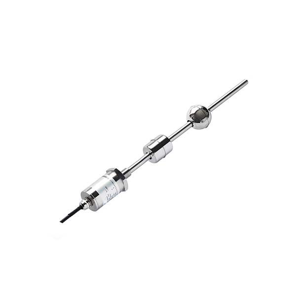
A magnetostrictive level transmitter is a probe that stands vertically in a tank with a ring-shaped float around it. A magnet inside the float marks the liquid surface. The electronics send a current pulse down a waveguide wire inside the probe; where the pulse meets the float magnet, the wire twists and a mechanical wave travels back to the head. The time between pulse and return gives the float position, and therefore the level, to fractions of a millimetre — regardless of foam, vapour, dielectric constant or liquid density.
How does a magnetostrictive level transmitter work, step by step?
The measurement is a time-of-flight measurement along a wire, not through the liquid or the air above it. That is why it is unaffected by what happens in the tank head space. The diagram shows the three steps.
- Interrogation pulse. The electronics send a short current pulse along a ferromagnetic waveguide wire that runs the full length of the probe. The pulse carries a circular magnetic field with it.
- Torsion at the float. The float carries a permanent ring magnet. Where the moving circular field crosses the magnet’s axial field, the waveguide twists for a moment (the Wiedemann effect). This launches a torsional, ultrasonic-frequency wave in both directions.
- Timing and conversion. A pickup in the head detects the returning wave. The wave travels at about 2,830 m/s, so the travel time converts directly into distance from the head. The transmitter subtracts that from the probe’s zero point and outputs level as 4–20 mA (the analogue signal range defined by IEC 60381-1 for direct-current process signals ↗), HART or RS485 Modbus.
For the same principle applied to hydraulic cylinders and machine axes, see how a magnetostrictive position sensor works.
How fast is the measurement? Worked timing example
The table converts float distance into wave travel time at 2,830 m/s. All values are calculated, not measured. Real update rates also include the electronics’ filtering and averaging, which are confirmed per model.
| Float distance from head | Travel time (calculated) | Typical SEGMENsensor model with this probe length |
|---|---|---|
| 1 mm | ≈ 0.35 µs | — |
| 1000 mm | ≈ 0.35 ms | SGM-LC10 (25–1000 mm) |
| 4000 mm | ≈ 1.41 ms | SGM-LK10 (25–4000 mm) |
| 8000 mm | ≈ 2.83 ms | SGM-LS10 (25–8000 mm), SE-LX10/20/30 (200–8000 mm) |
Because the wave travels in the wire, not in the tank, the result does not depend on vapour, foam, tank pressure, liquid density or dielectric constant. Only the float has to follow the surface.
How do floats set what you measure: level, interface or both?
The float is the part that touches the process, and it decides what the transmitter measures. Its density must be lower than the liquid it should ride on.
- One float — total level. The float rides on the top surface. This is the standard arrangement for water, fuel, oil and chemical tanks.
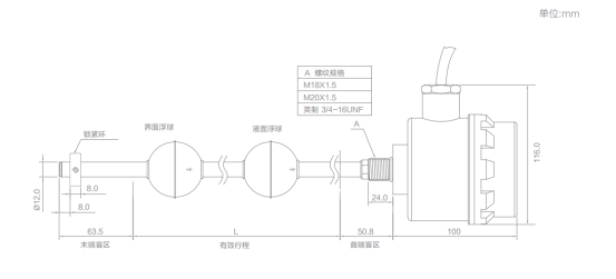
- Two floats — level plus interface. A second float is weighted to sink through the lighter liquid (for example oil) and ride on the heavier one (water). The head receives two echoes and reports total level and interface level from one probe. SE-LX10, SE-LX20 and SE-LX30 support this.
- Float material. Stainless steel floats suit water and hydrocarbons; for strong acids and alkalis the SGM-LC10 uses a PFA float and flange with a PP head.
- Dead zones. The float cannot reach the very top and bottom of the probe, so the active range is shorter than the probe length. State the tank height and nozzle position, and the probe length and dead zones are set when the order is confirmed.
How accurate is a magnetostrictive level transmitter?
Accuracy depends on the model and the output. These are the published figures for SEGMENsensor level models:
- SGM-LS10 and SGM-LK10 — repeatability ±0.005 mm.
- SGM-LC10 — non-linearity <±0.05%, with a 16-bit D/A analogue output.
- SE-LX10 / SE-LX20 / SE-LX30 — non-linearity ±1 mm, repeatability ±1 mm or ±0.1 mm, resolution 1 mm or 0.1 mm.
In the tank, the practical limits are usually the float, not the electronics: a float that sticks on deposits, rides lower in a lighter liquid than specified, or is disturbed by a fill stream. Use a stilling well near fill nozzles and give the liquid density at order so the float is sized correctly. Converting level to volume in a horizontal or dished tank is done in the PLC or DCS.
Which SEGMENsensor magnetostrictive level model fits my tank?
| Model | Range | Probe / materials | Outputs | Protection | Typical use |
|---|---|---|---|---|---|
| SGM-LS10 | 25–8000 mm | 304 stainless tube, M18×1.5 or custom fitting | 4–20 mA, 0–20 mA, 0–10 V, 0–5 V, RS485 | IP68, -40 to +85 °C | Process and storage tanks |
| SGM-LK10 | 25–4000 mm | Slim rod, M18×1.5 or M22×1.5, cable exit option | 4–20 mA, 0–10 V, 0–5 V, RS485 | IP68, -40 to +85 °C | Machine reservoirs, hydraulic oil tanks |
| SGM-LC10 | 25–1000 mm | PP head, PFA float and flange | 4–20 mA, 0–20 mA, 0–10 V, 0–5 V, RS485 Modbus RTU | IP68, -40 to +85 °C | Acid and alkali tanks |
| SE-LX10 | 200–8000 mm | Straps onto a magnetic level indicator or bypass chamber | 4–20 mA + HART, 0–10 V, RS485 | Flameproof, IP67 | Adding a signal to an existing level gauge |
| SE-LX20 | 200–8000 mm | Rigid 304 stainless rod, DN25 / DN50 / DN100 flange | 4–20 mA + HART, 0–10 V, RS485 | Flameproof, IP67 | Fuel, solvent and oil tanks; interface |
| SE-LX30 | 200–8000 mm | Φ18 mm stainless corrugated flexible probe | 4–20 mA + HART, 0–10 V, RS485 | Flameproof, IP67 | Tall tanks with limited headroom |
SE-LX rods are rated -40 to +85 °C, or -40 to +250 °C in the high-temperature version. Supply is 24 V DC as standard, with 12 V and 5 V ranges depending on output and model. ATEX/IECEx versions are optional; the Ex marking is as stated on the certificate of the supplied model, under the IECEx certification system for equipment used in explosive atmospheres ↗. IP67 and IP68 are defined in IEC 60529 (degrees of protection provided by enclosures) ↗. All models are on the magnetostrictive level transmitter page.
Download the one-page datasheet (PDF)
Range, outputs, materials, temperature limits and ordering codes for the two most-requested level models. No registration required.
Specifying a magnetostrictive level transmitter for an OEM project?
Send the tank height, nozzle position, liquid and its density, temperature, hazardous-area zone and PLC input. Our engineers propose the model, probe length and float. Qualification samples 1–5 pcs in 5–7 working days; production planned around annual volume · FOB China · reply within 24 hours.
Magnetostrictive vs hydrostatic and float switches: when to choose which?
- Choose magnetostrictive when you need continuous level to fractions of a millimetre, interface measurement, or a reading that ignores density, foam and vapour — inventory tanks, fuel and solvent storage, hydraulic reservoirs, dosing tanks.
- Choose a hydrostatic (submersible) sensor for wells, deep sumps and open water tanks where a rigid probe is impractical. It reads pressure, so the density must be known. See how a hydrostatic level sensor works.
- Choose float switches when you only need on/off points for pump control or high/low alarms. See the liquid level sensor selection guide.
Frequently Asked Questions
It times a torsional wave along a waveguide wire. A current pulse runs down the wire, twists it at the float magnet (Wiedemann effect), and the returning wave travels back at about 2,830 m/s. Travel time gives the float position, and the float position gives the level.
Not the measurement itself, because the wave travels in the wire, not in the liquid. Density only matters for the float: it must be lighter than the liquid so it rides on the surface. Give the liquid density at order so the float is sized correctly.
Yes. With two floats, one rides on the top surface and a heavier one sinks through the oil to ride on the water. SEGMENsensor SE-LX10, SE-LX20 and SE-LX30 report total level and interface from one probe over 200–8000 mm.
SEGMENsensor level models reach 8000 mm: SGM-LS10 covers 25–8000 mm and the SE-LX series 200–8000 mm. SGM-LK10 covers 25–4000 mm and the PP/PFA SGM-LC10 25–1000 mm. For tanks with limited headroom, the SE-LX30 uses a flexible probe.
Yes. The SE-LX series is flameproof with ATEX/IECEx options; the Ex marking is as stated on the certificate of the supplied model. SE-LX rods run from -40 to +85 °C, or -40 to +250 °C in the high-temperature version.