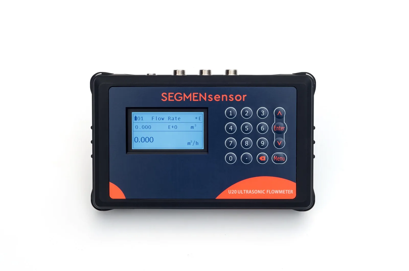
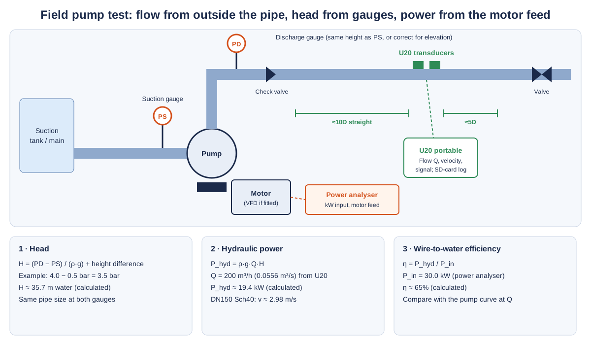
Clamp the U20 portable meter on a straight, full section of the pump discharge or branch pipe, enter the measured outside diameter, wall thickness and lining, and log flow while you read the suction and discharge gauges and the motor input power. Hydraulic power ρ·g·Q·H divided by input power gives wire-to-water efficiency. Use the same meter to compare branch flows with design for balancing and acceptance. Gas, steam, slurries, partly filled pipes and hazardous areas are not suitable.
Why Do Energy Audits Need a Portable Flow Meter?
Because most pumping systems have no flow meter at the points an auditor needs, and the ones that exist are often unverified. Pressure gauges and motor power are easy to read; flow is the missing variable that turns them into an efficiency, a system curve or a saving estimate. The U.S. Department of Energy's Improving Pumping System Performance: A Sourcebook for Industry builds its system assessment on exactly these measurements — flow, head and power — taken on the operating system rather than read from the nameplate.
A portable clamp-on ultrasonic flow meter fills that gap without a shutdown or a hot-work permit. Its transducers send ultrasonic pulses through the pipe wall with and against the flow; the transit-time difference gives velocity, and the inner area of the pipe gives volume flow. The method for liquids in closed conduits is described in ISO 12242 — Measurement of fluid flow in closed conduits: ultrasonic transit-time meters for liquid. Because nothing is cut, one meter can visit every pump, header and branch in a plant within a few days.
Typical Measuring Tasks for Audits, Testing and Commissioning
The table lists the jobs energy service companies, test and balance contractors and plant engineers most often use a portable meter for. Pipe sizes and temperatures are typical values for orientation only; model data are from the SEGMENsensor product page and datasheets.
| Task | Typical pipe | Medium · temperature | Meter · sensors | Confirm on site |
|---|---|---|---|---|
| Pump efficiency test (wire-to-water) | Steel discharge pipe, DN80–DN400 | Cooling, process or clean water, ambient | U20 with P2 sensors (−40 to +80 °C) | Straight run after the pump and check valve; gauge positions and heights; power analyser on the motor or drive feed |
| System flow survey for an energy audit | Headers and mains, DN100–DN1200 | Chilled, condenser or process water | U20, 25–1200 mm | Measured OD and wall; internal scale on old steel mains; logging interval and duration |
| Hydronic balancing of branch circuits | Steel or copper branches, DN15–DN100 | Chilled or heating water | U20; F1 / F1H sensors for DN15–DN40 | Design flow per branch; insulation removal points; balancing valve positions |
| Commissioning and handover acceptance | New steel, stainless or plastic pipe, DN25–DN600 | Clean water after flushing | U20 | Pipe filled and vented; design duty points; speeds to test on a VFD |
| Heating water and condensate return (liquid only) | Steel, DN25–DN300 | Hot water up to +130 °C | U20 with P2H sensors (to +130 °C) | Water temperature; flashing or air in the return; burn-safe handling of hot pipe |
| Check of an installed fixed meter | Same pipe as the fixed meter, DN25–DN1200 | Clean water | U20 upstream or downstream of the fixed meter | Same flow period for both readings; enough straight run for both meters |
How Do You Test Pump Efficiency With a Clamp-On Meter?
Measure flow, head and electrical input power at the same time, at a steady duty point, then calculate. The procedure we recommend:
Choose the flow section
Pick a straight, full section of the discharge pipe with about 10D upstream and 5D downstream, clear of the pump outlet elbow, check valve and control valve. On a DN150 pipe that is about 1.5 m and 0.75 m.
Enter real pipe data
Measure the outside diameter with a circumference tape and the wall with an ultrasonic thickness gauge; enter material, lining and liquid. The meter calculates the transducer spacing.
Read head and power at a steady point
Read suction and discharge pressure at gauges of the same pipe size, correcting for any height difference between them, and the input kW with a power analyser on the motor or variable-speed drive feed.
Log, then calculate
Log flow on the SD card for several minutes at each duty point and use the average. Then calculate head, hydraulic power and efficiency as below, and repeat at other valve positions or drive speeds to plot the operating curve.
Worked example (calculated values): a pump delivers 200 m³/h in a DN150 Schedule 40 pipe (154.1 mm bore, about 2.98 m/s, well inside the U20 range of ±0.01 to ±12 m/s). Suction gauge 0.5 bar, discharge gauge 4.0 bar, both at the same height and on the same pipe size: head H = 3.5 × 10⁵ Pa ÷ (1000 kg/m³ × 9.81 m/s²) ≈ 35.7 m. Hydraulic power = ρ·g·Q·H = 1000 × 9.81 × 0.0556 × 35.7 ≈ 19.4 kW. With 30.0 kW measured at the motor feed, wire-to-water efficiency ≈ 19.4 ÷ 30.0 ≈ 65%. Compare the measured flow and head with the pump curve at the same flow: a pump running far to the left or right of its best efficiency point, or well below its curve, is the usual finding. Formal pump acceptance tests follow ISO 9906:2012 — Rotodynamic pumps: hydraulic performance acceptance tests, grades 1, 2 and 3; a field audit with a clamp-on meter is an operating-point assessment, not a substitute for a test-bed acceptance test.
How Accurate Is the Efficiency Result?
No better than the flow, head and power readings that go into it, and the flow reading is no better than the pipe data. The U20 is rated ±1% of reading, but its flow is velocity multiplied by the inner area you enter. In the example above, a 2 mm layer of internal scale reduces the real bore from 154.1 mm to 150.1 mm; if the clean bore is entered, the meter reads (154.1 / 150.1)² ≈ 1.054, about 5% high, and the calculated efficiency is 5% high too (calculated value). On old steel mains, check for scale at a nearby flange or a pipe section removed during earlier work, and enter the lining or scale thickness.
The other common errors are an elevation difference between the two gauges that is not corrected (each metre of height is about 0.098 bar), gauges on different pipe sizes without a velocity-head correction, and readings taken at different moments while the duty is changing. Log flow and read gauges and power during the same stable period.
Planning an audit or a pump test programme?
Tell us the pipe sizes and materials you will meet, liquid temperatures, how long you need to log at each point, the number of meters for your team and whether you need small-pipe F1 / F1H sensors. OEM volume supply · samples 1–5 pcs in 5–7 working days · production lead time and MOQ confirmed with the quotation · quotation within 24 hours.
How Is a Portable Meter Used for Hydronic Balancing and Acceptance?
By measuring each branch against its design flow and adjusting until the measured values match, then recording the final flows for the handover file. Example: a DN50 chilled water branch (52.5 mm bore) designed for 12 m³/h should run at about 1.54 m/s; if the U20 shows 9.6 m³/h (about 1.23 m/s), the branch is at 80% of design and its balancing valve, strainer or the index circuit needs attention (calculated values). Small terminal branches from DN15 to DN40 use the F1 / F1H sensors, rated 0 to +65 °C and 0 to +115 °C.
For acceptance, test at the design duty and, on a variable-speed pump, at one or two part-load speeds, logging long enough to show the flow is steady. The full mounting procedure is in the clamp-on flow meter installation guide and the installation video.
Installation Difficulties in Plant Rooms and How to Handle Them
Short straight runs
Plant rooms pack pumps, elbows and valves together. If 10D / 5D is not available, use the longest straight section, stay upstream of control valves rather than just after them, and compare readings at two positions: if they agree within a few percent, the profile is acceptable for an audit.
Insulated chilled water pipes
Cut a neat window in the insulation for the two transducers, keep the pipe dry under them, and reseal with vapour-tight tape afterwards so condensation does not start under the insulation.
Unknown pipe data on old systems
Drawings are often wrong after decades of changes. Measure OD and wall at the actual section; for lined or scaled pipe, enter the lining and its thickness, and check the signal strength and quality on the status screen.
Hot pipes and outdoor work
Use P2H sensors up to +130 °C and handle hot pipe with gloves. The transducers are IP68; keep the handheld unit off wet floors and out of direct spray.
Battery and logging time
One charge lasts about 16 hours. Plan longer logs around a recharge, and set the logging interval to the job — seconds for a pump test, minutes for a 24-hour load profile; the SD card holds up to 32 GB. Large pipes above DN300 need extra pairs of the 1.3 m straps joined to the two standard ones (loop length ≈ 3.14 × outside diameter).
What Can a Portable Ultrasonic Flow Meter Not Measure?
It measures flow of a single, clean, sound-conducting liquid in a full pipe — nothing else. Specifically, it is not suitable for:
- Head and power: pressure gauges or transmitters and a power analyser are still needed for any efficiency calculation.
- Compressed air, gas and steam: liquids only. For steam systems, measure the condensate return as liquid where it is not flashing.
- Partly filled pipes and gravity drains: the pipe must be full at the measuring section.
- Slurries, heavily aerated returns and raw sewage: solids and bubbles scatter the transit-time signal.
- Flexible hoses and pipes below 15 mm: the pipe list covers rigid pipes; the smallest sensors cover DN15–DN40.
- Classified hazardous areas: the U20 is battery powered and has no explosion-protected version.
U20 Specifications That Matter for Field Testing
The values below are taken from the SEGMENsensor U20 portable flow meter page, the ultrasonic flow meter product page and the datasheets. For a permanent meter after the audit, compare models in the U10 to U20 model comparison.
| Parameter | U20 portable | Why it matters on an audit |
|---|---|---|
| Pipe size | 25–1200 mm (1–48 in); F1 / F1H sensors DN15–DN40 | One kit for pump mains and terminal branches |
| Accuracy · velocity | ±1% · ±0.01 to ±12 m/s | Covers part-load and full-load duty points |
| Sensor temperature | P2 −40 to +80 °C · P2H to +130 °C · F1 0–65 °C · F1H 0–115 °C | Chilled, condenser and heating water |
| Data | SD card up to 32 GB, logging interval 1–99999 s | Load profiles for savings estimates |
| Outputs | Choose two: 4-20 mA, RS485 Modbus, OCT pulse, relay | Feed a data logger or test rig alongside pressure and power |
| Power · display | 3000 mAh rechargeable lithium battery, about 16 hours · 240×128 backlit LCD | A full working day per charge |
| Liquids · certification | Single, acoustically conductive liquids in a full rigid pipe · sensors IP68 · CE, UKCA · no explosion-protected model | |
Download the one-page datasheet (PDF)
Pipe size ranges, accuracy, transducer types and temperature ratings, outputs, power supply, enclosure ratings and ordering code for the SEGMENsensor clamp-on ultrasonic flow meter range, including the U20. No registration required.
What Happens After the Audit?
The audit log usually decides where a permanent meter pays for itself. Where the survey shows a pump or circuit worth monitoring continuously, a fixed clamp-on meter goes on the same section the U20 used: the U10S PRO (±1%, 15–1200 mm) or the U11 (±0.5%, 15–5000 mm) with 4-20 mA or RS485 Modbus into the BMS or PLC, and an E-type energy meter with PT1000 sensors where cooling or heating energy must be metered. Data-centre and HVAC metering is covered in data center cooling water flow monitoring, pump discharge checks against installed meters in pump station flow verification, and plant cooling water in the power plant cooling water guide.
What Affects the Quotation?
We do not publish list prices on this page because the configuration drives the quotation: sensor set (P2, P2H, F1 / F1H), output options, cable length, extra straps for large pipes, energy-meter version and quantity. Quotations are FOB China and exclude international freight and import duties or taxes; payment is 100% T/T in advance, and meters carry a 12-month warranty.
Get a portable flow meter for audits, pump tests and commissioning
U20 portable for pump efficiency tests, system surveys, balancing and acceptance; U10S PRO, U11 or E-type energy meters for the permanent points the audit finds. OEM volume supply · samples 1–5 pcs in 5–7 working days · production lead time and MOQ confirmed with the quotation · quotation within 24 hours. Download the clamp-on flow meter datasheet (PDF).
Frequently Asked Questions
Yes. It supplies the flow, which is usually the missing measurement. Combined with the head from suction and discharge gauges and the input power from a power analyser, the flow gives the hydraulic power ρ·g·Q·H and the wire-to-water efficiency at that duty point.
About 16 hours on its 3000 mAh rechargeable lithium battery. Data are stored on an SD card of up to 32 GB at a logging interval you set between 1 and 99999 seconds; plan a recharge for longer logs.
Only a small window under the two transducers. The ultrasonic signal must pass from the transducer into bare pipe through couplant; on chilled water pipes, reseal the window with vapour-tight tape after the test.
Yes for liquid hot water up to +130 °C with P2H sensors, in a full pipe. It cannot measure steam, and condensate returns that flash or carry air give an unstable signal.
The U20 is rated ±1% of reading, but the result also depends on the pipe data and the head and power readings. A 2 mm internal scale layer not entered in a DN150 pipe makes flow and efficiency read about 5% high (calculated value).
Samples of 1–5 pcs ship in 5–7 working days. Production lead time and MOQ are confirmed with the quotation, which we send within 24 hours on working days, FOB China.