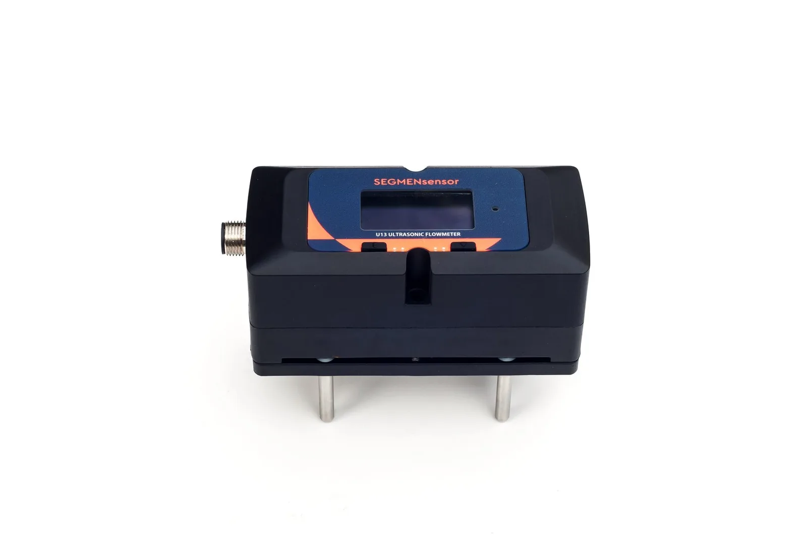
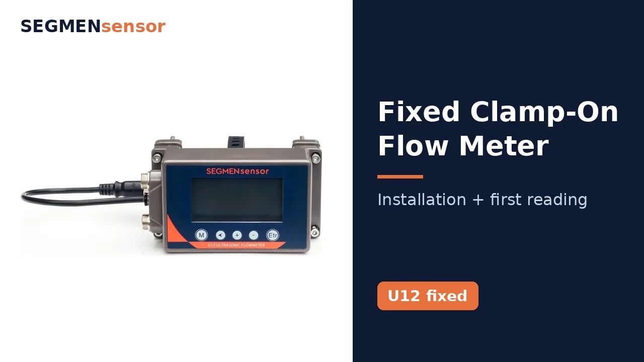
For flow measurement built into a machine, use a one-piece clamp-on meter on the machine's own pipe: the U13 for DN15–DN40, the U12 for DN15–DN65, and the U10S PRO or U11 wall-mount meters for larger skid headers. Reserve about 10D straight pipe upstream and 5D downstream in the skid layout, power the meter from the 24 V DC rail and read it over RS485 Modbus. Two-phase refrigerant, slurries, partly filled pipes and hazardous areas are not suitable.
Why Do Equipment Makers Choose a Clamp-On Meter?
Because it adds a measurement without adding anything to the hydraulic circuit. An inline meter means a flanged or threaded body in the pipe, a pressure drop the pump must cover, another wetted material to qualify for the liquid, and another joint to leak-test. A clamp-on transit-time meter sits outside the pipe: two transducers send ultrasonic pulses with and against the flow, and the time difference gives the velocity. The method for liquids in closed pipes is described in ISO 12242 — Measurement of fluid flow in closed conduits: ultrasonic transit-time meters for liquid.
For a machine builder that also means one meter family across several pipe sizes, no change to the pressure rating of the circuit and a meter that can be fitted after the pipework is welded and pressure-tested. The SEGMENsensor clamp-on ultrasonic flow meter range covers DN15 to DN5000 by model; for equipment, the compact one-piece U12 and U13 do most of the work.
Typical Measuring Points Inside OEM Equipment
The table lists the equipment types we are most often asked about. Pipe sizes and temperatures are typical values for orientation; model data are from the SEGMENsensor product pages and datasheets. Every new machine type is confirmed on qualification samples.
| Equipment · point | Typical pipe | Liquid · temperature | Suggested model | Confirm before ordering |
|---|---|---|---|---|
| Chiller or heat pump — evaporator / condenser water | Steel or copper, DN25–DN65 | Chilled water 5–15 °C; condenser water to about 40 °C | U12 with B1 sensor (0–65 °C) | Flow at full and minimum load; straight run after the pump; insulation window |
| Process or battery cooling unit — glycol loop | Stainless or steel, DN15–DN40 | Water–glycol, down to −10 °C | U13 with B1 sensor (−10 to +65 °C) | Glycol type and concentration for the liquid setting; lowest supply temperature |
| Heat exchanger unit — secondary circuit | Steel, DN80–DN300 | Heating water up to about 110 °C | U10S PRO or U11 with H1A sensors (to +130 °C); E-type with PT1000 for energy | Supply and return temperatures; transmitter mounting on the frame; AC or DC supply |
| Water treatment unit — feed, permeate, product water | Stainless, PVC or PP, DN15–DN50 | Clean water, ambient | U13 (DN15–DN40) or U12 (to DN65) | Pipe material and wall; lowest flow against the 0.15 m/s (U13) or 0.03 m/s (U12) limit |
| Hot water or heating module | Steel or copper, DN15–DN65 | Hot water up to 105–115 °C | U12 with B1H (0–115 °C) or U13 with B1H (−10 to +105 °C) | Maximum water temperature; dry, ventilated location for the electronics |
| Test rig or end-of-line test bench | Steel or stainless, DN15–DN300 | Test water, ambient | U12 / U13 on small lines; U11 (±0.5%) on larger lines | Required accuracy; calibration report; output to the test software |
How Do You Size the Meter for a Machine?
Start from the design flow and the lowest flow the machine will run at, convert both to velocity in the actual pipe bore, and check them against the model's range. Two worked examples (calculated values):
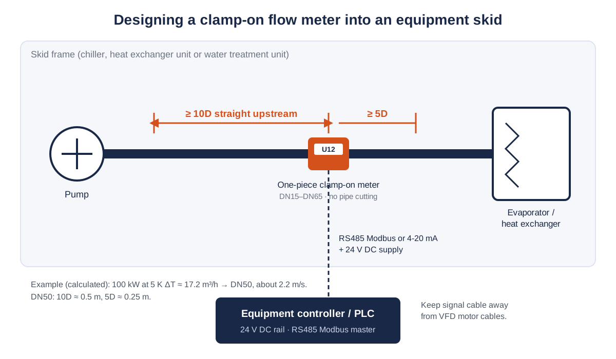
- Chiller, 100 kW at 5 K temperature difference: flow = 100 ÷ (4.19 × 5) ≈ 4.77 L/s ≈ 17.2 m³/h (286 L/min). In DN50 Schedule 40 pipe (52.5 mm bore) that is about 2.2 m/s, and about 0.55 m/s at 25% flow on a variable-flow machine — inside the U12 range of 0.03–10 m/s and below its DN50 upper limit of 600 L/min.
- Water treatment unit, product water 1.5 m³/h (25 L/min): in a 1-inch pipe (26.6 mm bore) the velocity is about 0.75 m/s, and the U13 DN25 flow range is 1–150 L/min. If the machine also runs a flushing or stand-by flow below about 0.15 m/s, that point is outside the U13 range; use the U12 (from 0.03 m/s) or a smaller pipe at the meter.
The upper flow limits of the U12 are 60, 100, 200, 300, 400, 600 and 1000 L/min for DN15 to DN65; the U13 flow ranges run from 0.55–60 L/min (DN15) to 2.5–400 L/min (DN40). The full tables are in the U10 to U20 model comparison, and low-flow behaviour is explained in flow meter turndown ratio.
How Is the Meter Wired Into the Machine Controller?
From the same 24 V DC rail that feeds the controller, with RS485 Modbus or 4-20 mA back to it. The U12 accepts 10–24 V DC (allow 1 A in the power budget), the U13 20–28 V DC through an M12 connector, and the U10S PRO and U11 10–36 V DC, with 90–245 V AC as an option. On the U12, any two of 4-20 mA, RS485 Modbus, OCT pulse and relay can be chosen; the U13 has 4-20 mA and RS485 Modbus with an optional pulse or relay alarm output. The serial protocol is Modbus, so the controller reads flow, totaliser and status as registers; confirm the register list with our engineers before you write the controller program.
Two practical rules from integration work: run the RS485 and 4-20 mA cables away from variable-speed drive motor cables, and ground the shield at one end. The electromagnetic behaviour of the finished machine is tested by the equipment maker under the generic standards it declares, such as IEC 61000-6-2:2016 — EMC immunity standard for industrial environments; CE and UKCA certificate copies for the meter are available on request with the quotation.
Designing flow measurement into a new machine?
Send the pipe sizes and materials at the measuring point, liquid and temperature range, design and minimum flow, supply voltage, the outputs your controller reads, branding needs and the expected annual volume. OEM volume supply · qualification samples 1–5 pcs in 5–7 working days · production lead time and MOQ confirmed with the quotation · quotation within 24 hours.
What Can Be Customised for an OEM Machine?
The faceplate and nameplate with your brand and model code, the display menu language, neutral packaging, the output combination, cable length and the calibration paperwork. On the U12, LoRa or 4G communication can be customised and the sensor cable is 2 m as standard, up to 5 m. A version without a display, other housing designs or a protocol other than Modbus are not in the datasheet and are evaluated per project. Each meter can ship with a factory calibration report, and three-point calibration is available. The branding steps for resellers are described on the private-label clamp-on flow meter page; this page covers the engineering side of building the meter into a machine.
A typical OEM project runs: your specification and piping drawing → our model and mounting proposal → 1–5 qualification samples in 5–7 working days → your tests on the prototype machine → order confirmation with production lead time and MOQ → production, flow test and calibration in our Shenzhen factory.
Installation Difficulties Inside Equipment and How to Handle Them
No straight run in a compact skid
Reserve it in the piping drawing rather than looking for it later: about 10D upstream and 5D downstream, measured from pumps, elbows and valves. On DN25 that is only about 0.25 m and 0.13 m. Where it cannot be had, place the meter upstream of control valves and confirm the reading on the prototype against a reference meter.
Vibration from compressors and pumps
Mount the meter on a rigid, supported pipe section away from compressor discharge lines and flexible connectors, and fix the transducer cable so it cannot chafe. Check signal strength and quality on the prototype with the compressor running.
Condensation on chilled water and glycol pipes
Fit the transducers on bare, dry pipe with couplant, then insulate over them with vapour-tight insulation so water does not collect under the sensors. Keep the meter electronics out of the drip path.
Same settings on every machine
Pipe outside diameter, wall thickness, material and liquid are set in the meter. For series production, fix them per machine type and include a signal-quality check and a flow comparison in your end-of-line test.
Plastic and thin-walled pipe
PVC, PP and stainless tube work well when the wall data are right. Measure the real wall on the first parts from your pipe supplier; a wrong wall thickness changes the bore used in the flow calculation.
Where Is a Clamp-On Meter Not Suitable in Equipment?
It needs a full pipe of a single, clean, sound-conducting liquid. It is not suitable for:
- Refrigerant lines: two-phase or flashing refrigerant scatters the signal; measure the water or glycol side instead.
- Slurries, sludge and liquids with heavy solids or air: the U12 and U13 are specified for liquids without solid particles or impurities.
- Partly filled pipes, gravity drains and tank overflows: the measuring section must stay full.
- Pipes below DN15 and flexible hoses: the U12 needs at least 12 mm inner diameter; hoses do not give a stable acoustic path.
- Temperatures outside the sensor ratings: for example glycol below −10 °C on the U13, or water above 115 °C on the U12; larger skids use the A2 (−40 to +80 °C), H1A (to +130 °C) or H2A (to +180 °C) sensors with the U10S PRO or U11.
- Explosion-protected machines: there is no explosion-protected model; machines for classified hazardous areas are not suitable.
Specifications of the Models Used in OEM Equipment
All values are taken from the SEGMENsensor ultrasonic flow meter product page and datasheets.
| Parameter | U13 one-piece | U12 one-piece | U10S PRO / U11 wall-mount |
|---|---|---|---|
| Pipe size | DN15–DN40 | DN15–DN65 (min. ID 12 mm) | 15–1200 mm / 15–5000 mm |
| Accuracy | <3% FS (<1.5% FS calibrated) | ±2% (±1% calibrated) | ±1% / ±0.5% |
| Velocity | 0.15–10 m/s | 0.03–10 m/s | ±0.03 to ±5 m/s / ±0.01 to ±12 m/s |
| Outputs | 4-20 mA + RS485 Modbus; OCT or relay optional | Two of 4-20 mA, RS485 Modbus, OCT, relay; LoRa / 4G customisable | Two of 4-20 mA, pulse (OCT), relay, RS232 / RS485 Modbus; HART optional |
| Supply | 20–28 V DC, M12 connector | 10–24 V DC | 10–36 V DC; 90–245 V AC optional |
| Sensor temperature | B1 −10 to +65 °C · B1H −10 to +105 °C | B1 0–65 °C · B1H 0–115 °C | A2 −40 to +80 °C · H1A to +130 °C · H2A to +180 °C |
| Housing · certification | PP glass-fibre, acid- and alkali-resistant · CE, UKCA | Metal, IP65 · CE, UKCA | IP65 transmitter, IP68 sensors · CE, UKCA |
Download the one-page datasheet (PDF)
Pipe size ranges, accuracy, transducer types and temperature ratings, outputs, power supply, enclosure ratings and ordering code for the SEGMENsensor clamp-on ultrasonic flow meter range. No registration required.
Related Applications
A chiller rating under AHRI's water-cooled water-chilling package certification programme (AHRI 550/590) is a laboratory test; a meter built into the machine is for control, protection and energy reporting in operation, not a substitute for the rating test. For the sites your machines go to, see data center cooling water flow monitoring and ultrapure water and battery liquid cooling; mounting steps are in the clamp-on flow meter installation guide and the U13 installation video.
What Affects the Quotation?
We do not publish list prices on B2B pages because the configuration drives the quotation: model, sensor type, outputs, supply, cable length, branding, packaging, calibration paperwork and annual volume. Quotations are FOB China and exclude international freight and import duties or taxes; payment is 100% T/T in advance, and meters carry a 12-month warranty.
Request qualification samples for your machine
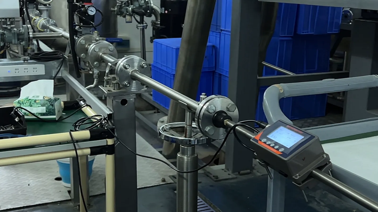
U13 and U12 one-piece meters for DN15–DN65 machine pipes, U10S PRO and U11 for larger skid headers, E-type energy meters where heat or cooling energy is reported. OEM volume supply · qualification samples 1–5 pcs in 5–7 working days · production lead time and MOQ confirmed with the quotation · quotation within 24 hours. Download the clamp-on flow meter datasheet (PDF).
Frequently Asked Questions
Yes. It clamps on a straight, full section of the machine's water or glycol pipe, adds no wetted part or pressure drop, runs from a 24 V DC rail and reports flow over RS485 Modbus or 4-20 mA. Refrigerant lines are not suitable.
The U13 for DN15–DN40 (0.15–10 m/s, PP glass-fibre housing, 20–28 V DC) and the U12 for DN15–DN65 (0.03–10 m/s, ±2% or ±1% after calibration, 10–24 V DC). Larger skid headers use the U10S PRO or U11.
Plan about 10 pipe diameters upstream and 5 downstream of the meter, away from pumps, elbows and valves: about 0.5 m and 0.25 m on DN50. Where the layout cannot give it, confirm the reading on the prototype machine.
Your brand on the faceplate and nameplate, menu language, packaging and output combination are standard OEM options, and LoRa or 4G can be customised on the U12. A version without display, other housings or protocols other than Modbus are evaluated per project.
The U13 B1 sensor is rated −10 to +65 °C, and the A2 sensors of the U10S PRO and U11 −40 to +80 °C. The U12 B1 sensor starts at 0 °C. Enter the glycol mixture as the liquid and confirm the reading on samples.
Qualification samples of 1–5 pcs ship in 5–7 working days. Production lead time and MOQ are confirmed with the quotation, which we send within 24 hours on working days, FOB China.