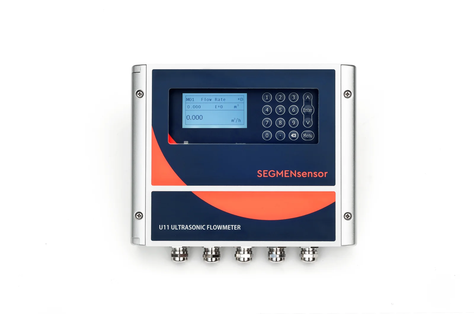
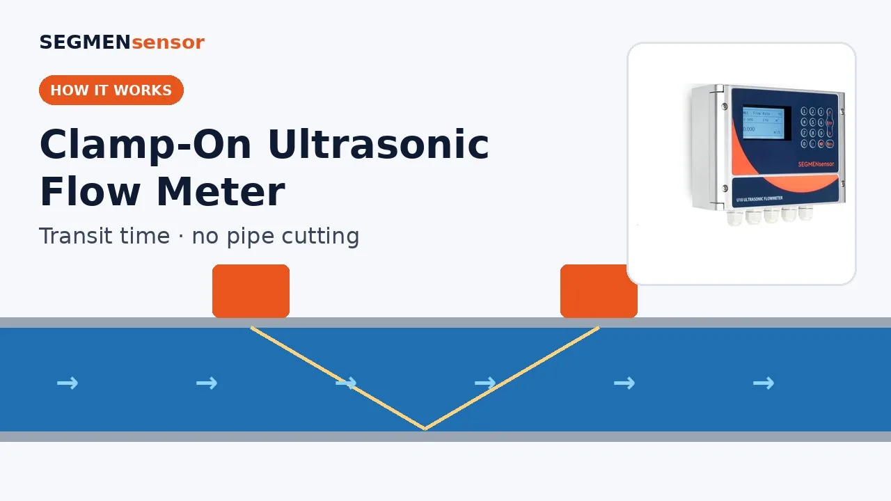
A clamp-on ultrasonic flow meter clamps two transducers on the outside of a full pipe and times ultrasonic pulses sent with and against the flow. The pulse travelling with the flow arrives sooner. That time difference, usually tens of nanoseconds, is proportional to velocity; velocity times the inner pipe area, corrected for the flow profile, gives the flow rate.
How does a clamp-on ultrasonic flow meter measure flow, step by step?
It measures two travel times and subtracts them. Every measurement cycle repeats the same four steps, many times per second, and averages the result.
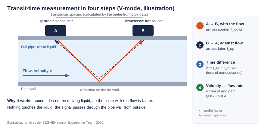
- Send with the flow. The upstream transducer A emits a short ultrasonic burst. It crosses the pipe wall, travels through the liquid at an angle, reflects off the far wall (V-mode) and reaches transducer B. The meter records the travel time tdown.
- Send against the flow. Transducer B fires back along the same path to A. The meter records tup.
- Subtract. Moving liquid carries the sound with it, so tdown is shorter than tup. With no flow the two times are equal and the difference is zero; with reverse flow the sign changes.
- Convert. The meter turns the time difference into the velocity along the sound path, applies a profile factor to get the mean velocity over the pipe area, and multiplies by the inner area to get the flow rate. Totalisers, 4–20 mA and Modbus outputs are all derived from this value.
Because the transducers sit outside the pipe, there is no cutting, no pressure drop and nothing in contact with the liquid. Installation details are covered in our clamp-on flow meter installation guide.
What is the transit-time formula?
For a sound path of length L in the liquid, crossing the pipe at angle φ to the wall normal, with sound speed c and path velocity v:
tdown = L / (c + v·sin φ) tup = L / (c − v·sin φ)
v = L / (2·sin φ) × (1/tdown − 1/tup)
Δt = tup − tdown ≈ 2·X·v / c² (X = axial length of the path = L·sin φ)
Q = k × v × π·D² / 4 (D = inner diameter, k = profile factor)
Two points follow from the equations. First, the sound speed c cancels out of the exact velocity equation, so a change in liquid temperature does not shift the reading directly; the meter still needs c to set the refraction angle and transducer spacing at set-up. Second, Δt scales with X and v, which is why small pipes and very low velocities produce very small time differences and set the low end of a meter's range.
Worked example: what time difference does a real pipe produce?
All values below are calculated, not measured. Assumptions: 100 mm inner diameter, water at 20 °C (c = 1482.66 m/s), refraction angle in the water φ = 20°, V-mode (two traverses), path velocity 1.60 m/s.
| Step | Calculation | Result |
|---|---|---|
| Path length in water | L = 2 × 0.100 m / cos 20° | 0.2128 m |
| Axial path length | X = 2 × 0.100 m × tan 20° | 0.0728 m |
| Downstream time | tdown = L / (c + v·sin φ) | 143.497 µs |
| Upstream time | tup = L / (c − v·sin φ) | 143.603 µs |
| Time difference | Δt = tup − tdown | 106 ns |
| Reynolds number | Re = V·D / ν, ν = 1.004 × 10⁻⁶ m²/s | ≈ 1.5 × 10⁵ (turbulent) |
| Profile factor | k = 1 / (1.119 − 0.011·log₁₀ Re) | 0.942 |
| Mean velocity | V = k × v = 0.942 × 1.60 m/s | 1.51 m/s |
| Flow rate | Q = V × π × 0.100² / 4 | 42.6 m³/h (11.8 L/s) |
At 0.01 m/s on the same pipe the time difference falls to about 0.66 ns, which shows why the lowest measurable velocity depends on the electronics. In a real meter the measured times also include delays in the transducer wedges and pipe wall; the meter subtracts these using the pipe data entered at set-up. To convert the result to US gpm or other units, use the flow unit converter; to see how the measured velocity becomes flow rate through the pipe area, use the pipe flow rate calculator (velocity to flow rate).
Why does the meter need a profile factor and straight pipe?
Because the sound path measures the average velocity along a line across the pipe, not over the whole area. Liquid moves fastest in the centre and slowest at the wall. In laminar flow the line average is two-thirds of the centre velocity and the area average is one-half, so k = 0.75 exactly. In turbulent flow the profile is flatter and k is about 0.93–0.95. The factor is only valid for a fully developed profile, which is why the general rule is at least 10D of straight pipe upstream and 5D downstream, away from pumps, elbows and valves.
What are V, Z and W mounting modes?
They describe how many times the sound crosses the pipe between the two transducers. More crossings give a longer path and a larger Δt, but also more signal loss.
| Mode | Transducer position | Pipe crossings | Typical use |
|---|---|---|---|
| W | Same side | 4 | Small, clean, thin-walled pipes, about DN15–DN50 |
| V | Same side | 2 | Most pipes, about DN50–DN300 |
| Z | Opposite sides | 1 | DN300 and above, or when V-mode signal stays below 60% |
What makes a clamp-on flow meter read wrong?
| Symptom | Likely cause | What to do |
|---|---|---|
| Steady offset of a few percent | Wrong outside diameter or wall thickness (1% error in bore ≈ 2% flow error, calculated) | Measure OD with a tape and wall with an ultrasonic thickness gauge; re-enter |
| Reading drifts or jumps | Too close to an elbow, pump or valve | Move to a point with 10D upstream and 5D downstream of straight pipe |
| Signal strength below 60% | Dry couplant, paint or scale, wrong spacing | Clean to bare metal, fresh couplant, check spacing; try Z-mode |
| No reading or alarm | Pipe not full, or heavy air or solids | Choose a point that always runs full, such as a vertical riser with upward flow |
| Reading not zero at no flow | Zero offset after installation | Re-check the pipe data, then apply a zero set with the line full and flow stopped, if the model offers it |
Which SEGMENsensor clamp-on meters use this principle?
All six models are transit-time meters for full pipes carrying a single, clean liquid. Figures are from the published datasheets; see the clamp-on ultrasonic flow meter range or the model comparison for full specifications.
| Model | Pipe size | Velocity range | Accuracy |
|---|---|---|---|
| U11 wall-mount | 15–5000 mm | ±0.01 to ±12 m/s | ±0.5% (0.1% repeatability) |
| U10 wall-mount | 25–1200 mm | ±0.03 to ±5 m/s | ±1% (0.2% repeatability) |
| U10S PRO wall-mount | 15–1200 mm | ±0.03 to ±5 m/s | ±1% (0.2% repeatability) |
| U20 handheld | 25–1200 mm | ±0.01 to ±12 m/s | ±1% |
| U12 one-piece | DN15–DN65 | 0.03–10 m/s | ±2% (±1% after calibration) |
| U13 compact | DN15–DN40 | 0.15–10 m/s | <3% FS (<1.5% FS after calibration) |
For the difference between this method and reflection-based meters, read transit-time vs Doppler ultrasonic flow meters. For portable spot checks, see the U20 portable clamp-on flow meter.
Need a clamp-on flow meter for your pipe?
Send the pipe outside diameter, wall thickness, material, liquid, temperature and flow range. Our engineers recommend the model and transducers. Qualification samples of 1–5 pcs in 5–7 working days · production lead time and MOQ confirmed with the quotation · FOB China · 100% T/T in advance · reply within 24 hours.
Frequently Asked Questions
Partly. In the exact transit-time equation the speed of sound cancels out, so velocity comes from the two transit times and the path geometry. The meter still uses the sound speed of the liquid and the pipe material to work out the refraction angle and the transducer spacing, so select the correct liquid and pipe material at set-up.
Yes. The ultrasonic pulse must cross a continuous column of liquid between the two transducers. An air gap at the top of a partly filled pipe blocks the signal, and the meter shows a low-signal alarm or no reading. Choose a measuring point where the pipe always runs full, such as a vertical riser with upward flow or a low point in a horizontal run.
Yes. When the flow reverses, the upstream and downstream transit times swap and the time difference changes sign, so the meter reads negative flow. SEGMENsensor U11 and U20 meters measure ±0.01 to ±12 m/s and the U10 series ±0.03 to ±5 m/s in both directions.
The meter converts the velocity along the sound path into the mean velocity over the pipe area with a profile factor that assumes a fully developed flow profile. Elbows, valves and pumps distort the profile, so the factor no longer fits. As a general rule allow at least 10 pipe diameters of straight pipe upstream and 5 diameters downstream of the transducers.
It depends on the model and the installation. SEGMENsensor specifies ±0.5% with 0.1% repeatability for the U11, ±1% for the U10 series and U20 (0.2% repeatability on the U10 series), ±2% for the U12 (±1% after calibration) and less than 3% FS for the U13 (less than 1.5% FS after calibration). These figures assume correct pipe data, a full pipe and an adequate straight run.
Enter the pipe outside diameter, wall thickness, pipe material, any lining, the liquid type and the mounting mode (V, Z or W). The meter uses these values to calculate the transducer spacing and the inner pipe area. An error of 1% in the inner diameter gives about 2% error in flow rate, because area scales with diameter squared (calculated).