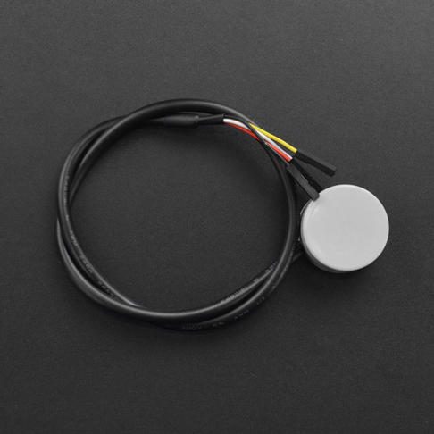
When an ultrasonic level sensor reads wrong, check the sound path first: is the liquid closer than the 0.25 m blind zone, is the beam hitting a ladder, pipe or nozzle wall, is there foam or a turbulent inlet stream, or is the sensor face wet? These cause most faults. Wiring and supply are checked only after the echo path is clear.
This guide is for OEM engineers, system integrators and maintenance teams who use or specify top-mounted ultrasonic level sensors on water tanks, wastewater sumps, chemical day tanks and coolant reservoirs. It explains the real disadvantages of ultrasonic level measurement, gives a symptom-by-symptom troubleshooting table, and shows when to change technology instead of fighting the installation. All SEGMENsensor figures come from the published SEU ultrasonic level sensor page and the liquid level sensor datasheet.
How Does an Ultrasonic Level Sensor Measure Level?
It sends a short sound pulse from the tank roof down to the liquid surface and times the echo. The distance is D = c × t ÷ 2, where c is the speed of sound in the air space and t is the round-trip time. Level is then L = E − D, where E is the empty distance from the sensor face to the tank bottom, and the transmitter outputs L as 4-20 mA.
Every problem in this guide breaks one of three assumptions in that formula: that the echo comes from the liquid surface (and not from something else), that the echo is strong enough to detect, and that c is known. The installation geometry, including the blind zone, is explained with a drawing on the SEU sizing section.
What Are the Disadvantages of Ultrasonic Level Sensors?
The main disadvantages are a blind zone directly below the sensor, sensitivity to foam, vapour and condensation, false echoes from tank internals, a reading that depends on air temperature, and unsuitability for vacuum. None of these matter on a clean, calm, open tank; all of them matter in some process vessels.
- Blind zone. The transducer needs time to stop ringing after it transmits, so the SEU cannot measure the top 25 cm. The maximum level must stay at least 0.25 m below the face.
- Foam. Dense foam absorbs the pulse and the echo becomes too weak to detect.
- Vapour and condensation. Heavy vapour scatters the pulse, and droplets or deposits on the face damp the transducer.
- False echoes. Ladders, pipes, agitator blades, weld seams and narrow nozzles return echoes that can be mistaken for the surface.
- Temperature dependence. The speed of sound in air changes by about 0.6 m/s per °C, so the sensor must compensate for the air-space temperature.
- No vacuum. Sound needs a gas to travel through; ultrasonic sensors are not used in vacuum vessels.
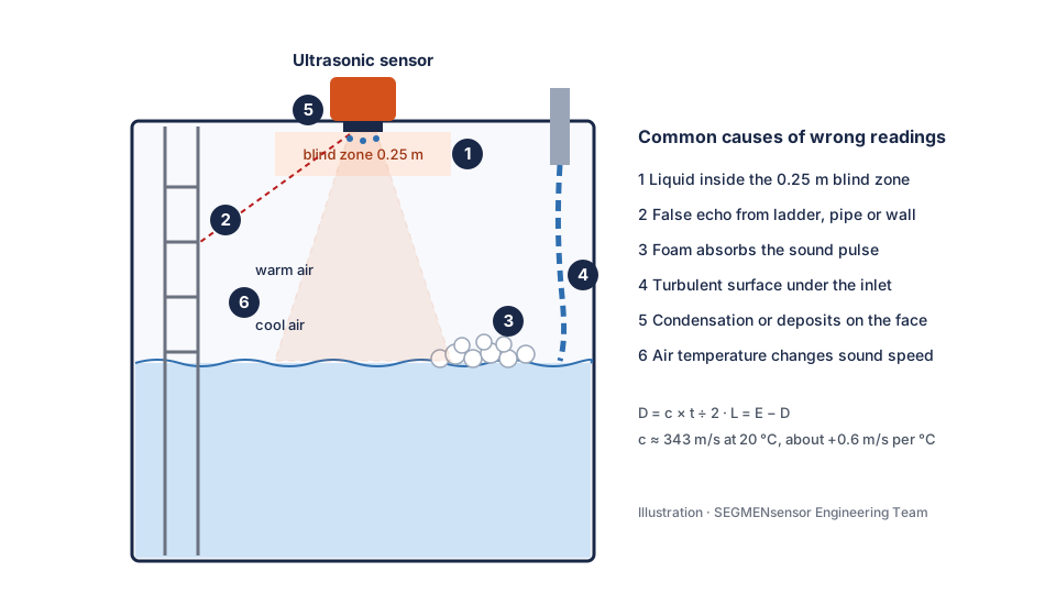
Ultrasonic Level Sensor Troubleshooting Table
Match the symptom you see on the PLC or display to the likely cause, then apply the fix. Numbers in the first column refer to the illustration above.
| Symptom | Likely cause | How to confirm | Fix |
|---|---|---|---|
| (1) Reading freezes or jumps when the tank is nearly full | Liquid has entered the 0.25 m blind zone | Measure the gap between the sensor face and the surface at maximum fill | Raise the sensor on a stand-off or nozzle so the face is at least 0.25 m above the highest level; re-span 20 mA to the working maximum |
| (2) Reading sticks at the same wrong level, often during emptying | False echo from a ladder rung, pipe, weld seam or nozzle wall | The wrong level matches the height of an internal object | Move the sensor away from internals and the tank wall so the beam has a clear path; keep any nozzle short and wide, with dimensions confirmed by our engineers |
| (3) Signal drops out or goes to a fault value | Foam absorbing the pulse | Faults coincide with foaming (dosing, aeration, agitation) | Remove the foam source or change to a submersible or magnetostrictive transmitter that measures below the foam |
| (4) Reading jumps while the tank is filling | Inlet stream or splashing in the beam; rough surface | Jumps stop when the fill pump stops | Mount the sensor away from the inlet; route the inlet below the surface; add damping in the PLC |
| (5) Erratic readings after cold nights or cleaning | Condensation, spray or deposits on the sensor face | Face is wet or coated on inspection | Clean the face; improve venting of the tank head space; choose the 316L face for aggressive media |
| (6) Level drifts slowly through the day | Air-space temperature differs from the temperature at the sensor | Drift follows sun or process heat on the tank roof | Shade the tank roof or sensor; state the air-space temperature range in the RFQ so the configuration is checked |
| Output fixed at or below 4 mA | No supply, reversed loop or too much loop resistance | Measure the voltage at the sensor terminals under load | Restore 12–36 V DC at the terminals; check cable length with the loop resistance calculator |
| Relay chatters at the alarm point | Surface ripple around a single switch point | Chattering stops when the surface is calm | Separate the on and off points so they do not coincide, or add a delay in the controller |
How Much Error Does Air Temperature Cause?
About 0.17% of the measured distance per °C of uncorrected temperature error, because sound speed changes by roughly 0.6 m/s per °C around 343 m/s. The error grows with the distance to the surface, so it is largest when the tank is nearly empty.
| Distance to surface | Error per 1 °C (calculated) | Error per 10 °C (calculated) |
|---|---|---|
| 2 m | ≈ 3.5 mm | ≈ 35 mm |
| 5 m | ≈ 8.7 mm | ≈ 87 mm |
| 10 m | ≈ 17.5 mm | ≈ 175 mm |
| 15 m | ≈ 26 mm | ≈ 262 mm |
Calculated as distance × 0.6 ÷ 343 per °C; these are planning values, not measured values. Ultrasonic transmitters compensate with a temperature sensor at the transducer, so the residual error comes from the difference between the air at the sensor and the average air in the beam path — for example a hot roof above a cool liquid. The metre and the kelvin used in these values are defined in the NIST SI units guide ↗.
SEU Ultrasonic Level Sensor Specifications
These are the published standard figures for the SEGMENsensor SEU series. Configurations outside this table are confirmed per project.
| Parameter | SEU series |
|---|---|
| Measuring principle | Ultrasonic pulse-echo (time of flight), non-contact |
| Measuring range | 0.25–15 m |
| Blind zone | 25 cm |
| Accuracy | ±0.3% FS |
| Output | 4-20 mA + 2 relays |
| Supply | 12–36 V DC |
| Operating temperature | −20 °C to +70 °C |
| Protection | IP67 |
| Sensor face material | ABS or 316L |
| Process connection | G¾ / G1 / flanged |
| Display | LCD (optional) |
| Compliance | CE, RoHS |
| Samples | 1–5 pcs for qualification in 5–7 working days; volume per project |
IP67 is defined by the IP code in IEC 60529 ↗: dust-tight and protected against temporary immersion. It is a rating for the housing, not for continuous submersion.
Download the one-page datasheet (PDF)
Range, blind zone, accuracy, outputs, supply, temperature, materials and process connections for the SEU ultrasonic sensor, alongside the float switch, submersible transmitter and coolant level sensor. No registration required.
More documents: liquid level sensor downloads
Ultrasonic sensor giving trouble on your tank?
Send the tank height and diameter, nozzle dimensions, medium, foam or vapour conditions, air-space temperature range, output and annual volume. Our engineers check whether ultrasonic fits or another technology is safer. Qualification samples (1–5 pcs) ship in 5–7 working days; production lead time and MOQ are confirmed with the quotation, and every inquiry is answered within 24 hours.
When Should You Not Use an Ultrasonic Level Sensor?
Do not use ultrasonic when the tank has dense foam, heavy vapour, a vacuum, or so many internals that no clear beam path exists. In those tanks a sensor that measures inside or below the liquid is more reliable.
| Tank condition | Better choice | Why |
|---|---|---|
| Dense foam, aeration | Submersible hydrostatic transmitter | Measures pressure at the bottom, below the foam |
| High-resolution gauging, interface level | Magnetostrictive level transmitter (25–8000 mm) | Float position on a rigid probe, unaffected by vapour |
| Only high/low alarms or pump control | Float level switch | Point switching without a beam path |
| Clean or dirty water, open sump, no foam | SEU ultrasonic sensor | Nothing touches the liquid, so nothing fouls |
For a full method across technologies, see how to choose a liquid level sensor; for water tanks and wells specifically, see the water level sensor selection guide. All SEGMENsensor level technologies are listed on the liquid level sensor overview.
Installation Checklist That Prevents Most Ultrasonic Problems
- Height: sensor face at least 0.25 m above the highest working level.
- Clear path: no ladders, pipes, agitators or inlet streams inside the beam; keep away from the tank wall.
- Perpendicular: mount the face level so the echo returns straight to the sensor.
- Nozzle: keep any nozzle short and wide and send its length and inner diameter with the RFQ.
- Span: 4 mA = empty, 20 mA = maximum working level; check the scaling with the 4–20 mA calculator.
- Environment: shade the sensor from direct sun and keep the operating range within −20 °C to +70 °C.
Factory Supply for OEM Equipment Builders
Segmen Industrial Development Co., Ltd. was founded in Shenzhen in 2019; its engineering team brings more than 20 years of sensor experience and supplies 200+ OEM customers in 30+ countries. Sensor electronics are checked at signal test stations before shipment, and quality is managed under ISO 9001:2015. Typical applications for the SEU include wastewater sumps, chemical day tanks, water storage tanks and coolant reservoirs, evaluated per project.
FAQ
Usually because the echo is coming from something other than the liquid surface, such as a ladder, pipe, nozzle wall or inlet stream, or because the liquid is inside the 0.25 m blind zone. Move the sensor to a clear beam path and keep the face at least 0.25 m above the highest level.
No, not reliably. Dense foam absorbs the sound pulse and the echo becomes too weak. Use a submersible hydrostatic transmitter or a magnetostrictive level transmitter, which measure below the foam. Light, thin foam is evaluated per project.
It is the distance directly below the sensor face where level cannot be measured, because the transducer is still ringing after it transmits. On the SEGMENsensor SEU it is 25 cm, so the measuring range starts at 0.25 m and goes to 15 m.
Yes. The speed of sound in air rises by about 0.6 m/s per °C, so an uncorrected 1 °C error shifts a 5 m reading by about 8.7 mm (calculated value). Sensors compensate with a temperature sensor at the transducer; large temperature gradients in the air space still cause drift.
Qualification samples of 1–5 pcs ship in 5–7 working days. Production lead time and MOQ are confirmed with the quotation, based on your annual volume, and every inquiry is answered within 24 hours.
References
Related reading: SEU ultrasonic level sensor · Liquid level sensors · Water level sensor selection guide · How to choose a liquid level sensor
Last updated: November 7, 2026 · SEGMENsensor Engineering Team