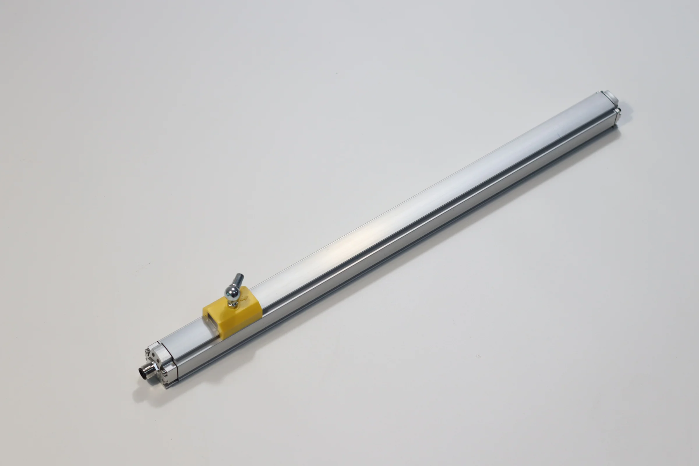
A linear potentiometer is a simple, low-cost contact sensor: a wiper slides along a resistive track and the output voltage follows position. A magnetostrictive sensor is non-contact: it times a strain pulse created by a moving magnet. Switch to magnetostrictive when the axis cycles constantly, vibrates, sees dirt or moisture, needs long strokes or must output a digital signal.
This guide is for machine builders, cylinder makers and maintenance engineers who already use linear potentiometers and are deciding whether to keep them or move to non-contact sensing. It explains how each technology works, compares them on the points that decide service life and signal quality, and gives a checklist for replacing a potentiometer without changing the controller. SEGMENsensor figures come from the magnetostrictive position sensor series page and the SGM-PE10 profile linear position sensor page.
What Is a Linear Potentiometer?
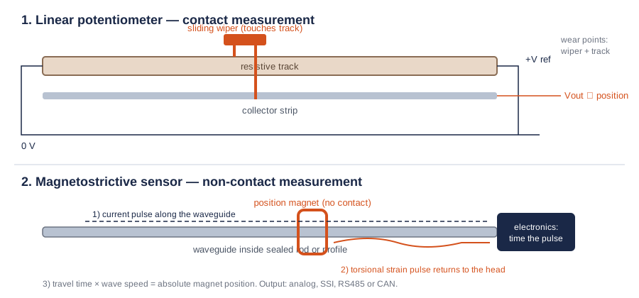
A linear potentiometer is a contact position sensor in which a sliding wiper touches a resistive track, so the voltage picked up by the wiper changes in proportion to its position. A reference voltage is applied across the track; the wiper divides it, and the controller reads the divided voltage as position.
The strengths are real: the electronics are minimal, the output is a plain voltage that almost any controller can read, and short-stroke units are compact. The limitation is built into the principle. The wiper and track rub together on every stroke, so the sensor wears, the contact can become noisy, and dust, moisture or vibration accelerate that wear. Service life depends on stroke count, speed, vibration and contamination, and is stated in each potentiometer's own datasheet.
What Is a Magnetostrictive Position Sensor?
A magnetostrictive position sensor is a non-contact sensor that measures the absolute position of a permanent magnet moving along a sealed waveguide. The electronics send a current pulse down the waveguide; where the pulse meets the magnet's field, a torsional strain pulse is created and travels back to the sensor head. The travel time gives the magnet position. The full principle is explained in how a magnetostrictive position sensor works.
Because the magnet never touches the waveguide, there is no sliding contact to wear. The position value is absolute, so the controller knows where the axis is immediately after power-up without a homing run.
Linear Potentiometer vs Magnetostrictive: Comparison Table
The table compares the two technologies on the points that decide service life, signal quality and integration effort. Magnetostrictive values are published SEGMENsensor figures; potentiometer values are general characteristics of the technology, so check the datasheet of the unit you use today.
| Criterion | Linear potentiometer | SEGMENsensor magnetostrictive sensor |
|---|---|---|
| Measuring principle | Wiper on a resistive track (voltage divider) | Time of flight of a strain pulse created by a moving magnet |
| Contact | Sliding contact on every stroke | Non-contact; magnet and waveguide never touch |
| Wear | Wiper and track wear with stroke count, speed and vibration | No wiper or track to wear |
| Position value | Absolute (ratio of reference voltage) | Absolute; no homing after power-up |
| Stroke | Depends on the model; typically short to medium strokes | 25–8000 mm (SGM-PE20, SGM-PF20, SGM-PR40, SGM-PR50: 25–4000 mm) |
| Linearity | Stated per model; can change as the track wears | Non-linearity below ±0.01% FS (SGM-PR10, SGM-PE10, SGM-PE20 family) |
| Output | Voltage divider output; transmitter needed for 4–20 mA or digital signals | 4–20 mA, 0–20 mA, 0–10 V, 0–5 V, 0.5–4.5 V, RS485, SSI per model; CAN, PROFINET and EtherCAT confirmed per model |
| Update time | Continuous analog signal | 1 ms on 1–2 m ranges (SGM-PE10) |
| Protection | Depends on the housing and seal of the model | IP67 (SGM-PE10, SGM-PE20) or IP68 (SGM-PR20, SGM-PF10 and others) |
| Operating temperature | Stated per model | -40 to +85 °C |
| Supply | Reference voltage from the controller | 24 V DC standard; 12 V and 5 V ranges depending on output and model |
| Inside a hydraulic cylinder | Not typical | Yes: in-cylinder pressure tube rated 35 MPa continuous, 70 MPa peak |
| Typical use | Low-duty axes, test rigs, simple feedback in clean environments | High-cycle machines, hydraulic cylinders, outdoor and wash-down equipment, long strokes |
When Should You Switch From a Linear Potentiometer to a Magnetostrictive Sensor?
Switch when the cost of replacing worn potentiometers, or of the downtime they cause, is higher than the cost difference between the two sensors. In practice, these conditions point to a magnetostrictive sensor:
- High cycle count: the axis moves continuously, for example on injection-moulding machines, presses or packaging lines, and potentiometers are replaced as wear parts.
- Noisy or jumping signal: the controller sees spikes or dropouts at positions the axis visits most often, a typical sign of track wear.
- Vibration and shock: mobile machines, crushers or vibrating feeders shake the wiper on the track.
- Dirt, moisture or wash-down: contamination reaches the track; IP67 or IP68 sealing is needed.
- Long stroke: the axis is longer than the potentiometers available in your envelope; magnetostrictive sensors reach 8000 mm.
- Digital or current output: the controller needs 4–20 mA over a long cable, SSI for closed-loop motion control, or RS485 or CAN on a bus.
- Position inside a hydraulic cylinder: the sensor must sit in the pressurized cylinder; see what a hydraulic cylinder position sensor does.
A potentiometer usually remains the sensible choice for short, low-duty axes in clean conditions, where the controller already reads a voltage divider and replacement is easy.
How Do You Replace a Linear Potentiometer With a Magnetostrictive Sensor?
Most replacements are made without changing the controller program, by matching the output signal and the mechanical interface. Use these steps:
- Record the existing signal. Note the voltage range the controller reads (for example 0–5 V or 0–10 V) and whether the reference voltage comes from the controller.
- Choose the output. Pick a magnetostrictive output that the controller input already accepts: 0–5 V, 0–10 V or 0.5–4.5 V for voltage inputs, 4–20 mA for current inputs, or SSI, RS485 or CAN for digital inputs.
- Check the supply. A magnetostrictive sensor needs its own supply, 24 V DC as standard; 12 V and 5 V ranges are available depending on output and model.
- Match the stroke and mounting. Give the electrical stroke and mounting dimensions. Profile sensors such as the SGM-PE10 or the slim SGM-PE20 (clamp hole spacing 42.5 mm or 50 mm) mount on a machine frame like a profile potentiometer.
- Choose the magnet. Use a slider magnet on a guided rail where the potentiometer had a push rod, or a floating magnet where a contact-free gap is needed.
- Verify the zero and full-scale points. Confirm the ends of the measuring range on the machine before production use.
SEGMENsensor Sensors for Potentiometer Replacement
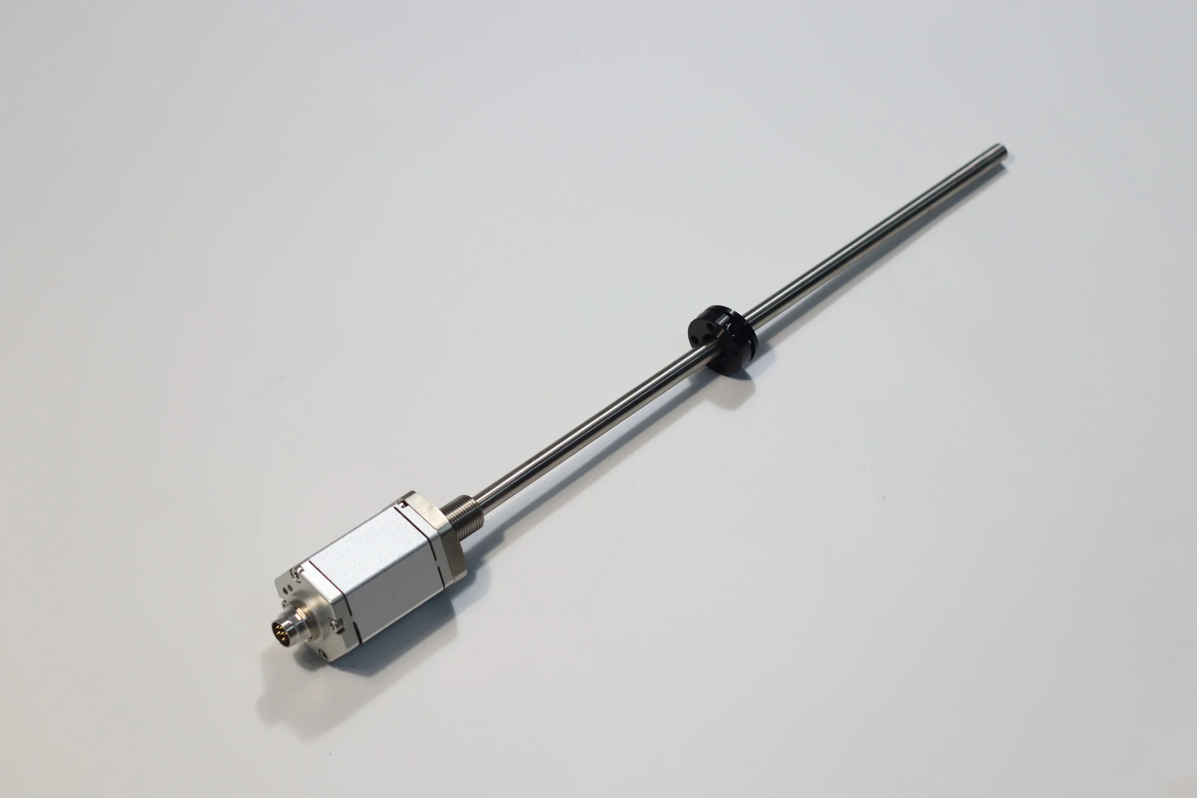
The table lists the SEGMENsensor series most often used where a linear potentiometer was fitted before. Values are taken from the series pages.
| Part number | Form | Range | Output | Protection |
|---|---|---|---|---|
| SGM-PE10 | Profile, slider or floating magnet | 25–8000 mm | 4–20 mA / 0–20 mA / 0–10 V / 0–5 V / RS485 / SSI | IP67 |
| SGM-PE20 | Slim profile | 25–4000 mm | 4–20 mA / 0–10 V / RS485 | IP67 |
| SGM-PF20 | Compact rod | 25–4000 mm | 4–20 mA / 0–10 V / 0.5–4.5 V / 0.25–4.75 V | IP68 |
| SE-PR30 | Intrinsically safe rod | 25–4000 mm | 0.5–4.5 V / 0–5 V / 4–20 mA / RS485 | IP67 / IP68 |
| SGM-PR10 | Rod, in-cylinder | 25–8000 mm | 4–20 mA / 0–20 mA / 0–10 V / 0–5 V / RS485 / SSI | IP67 |
Download the one-page datasheet (PDF)
Ranges, outputs, supply voltage, temperature limits, IP rating, dimensions and ordering codes for the SGM and SE position sensors. No registration required.
More documents: magnetostrictive downloads (per-series datasheets and ordering codes)
Not sure which output or magnet suits your existing potentiometer installation? Request an engineering review: send the current signal range, stroke and mounting, and an application engineer replies within 24 hours. Qualification samples of 1–5 pcs ship in 5–7 working days.
Factory Supply for Machine Builders
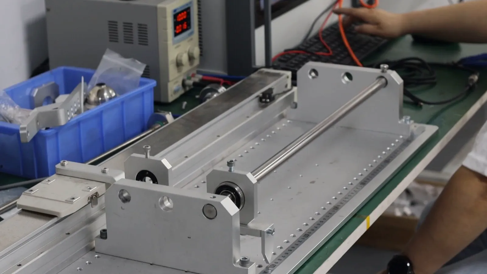
Segmen Industrial Development Co., Ltd. was founded in Shenzhen in 2019; its engineering team brings more than 20 years of sensor experience and supplies 200+ OEM customers in 30+ countries. Linear position sensors are tested on a linear test bench before shipment. Quality is managed under ISO 9001:2015, and products carry CE, RoHS 3 and UKCA, with ATEX/IECEx options and UL on selected models. Orders are quoted FOB China with 100% T/T in advance and a 12-month warranty.
FAQ
General questions
A linear potentiometer measures position with a wiper that slides on a resistive track, so it is a contact sensor that wears with use. A magnetostrictive sensor measures the position of a magnet that never touches the waveguide, so it is non-contact, has no wiper to wear and reports absolute position from power-up.
Accuracy depends on the specific models compared. SEGMENsensor SGM-PR10, SGM-PE10 and SGM-PE20 sensors have non-linearity below ±0.01% FS. A potentiometer's linearity is stated in its own datasheet and can change as the track wears, while a magnetostrictive sensor has no wearing contact.
The wiper and resistive track rub together on every stroke. Over time this wears the track and the contact, which causes noise, signal spikes or dropouts, usually at the positions the axis visits most. Vibration, dust and moisture speed up this wear.
Usually yes. Choose a voltage output that the controller input already reads, such as 0–5 V, 0–10 V or 0.5–4.5 V, and provide a separate supply, 24 V DC as standard. Match the stroke and mounting, then verify the zero and full-scale points on the machine.
A linear potentiometer remains sensible for short, low-duty axes in clean, dry conditions, where the controller already reads a voltage divider, the stroke count is low and a worn sensor is easy to replace.
Procurement Q&A
Send the electrical stroke, the voltage range the controller reads today, the available supply voltage, the mounting dimensions, how the moving part connects (push rod or slider), the environment and the annual volume. A written quotation follows within 24 hours on working days.
The SGM-PE10 profile sensor covers 25–8000 mm with 4–20 mA, 0–20 mA, 0–10 V, 0–5 V, RS485 or SSI output and IP67 protection. For strokes up to 4000 mm and tight frames, the slim SGM-PE20 offers clamp hole spacing of 42.5 mm or 50 mm.
Qualification samples of 1–5 pcs ship in 5–7 working days. Production lead time and MOQ are confirmed with the quotation, based on your annual volume.
References
- IEC 60529 — Degrees of protection provided by enclosures (IP code) ↗
- IEC 60381-1 — Analogue signals for process control systems: direct current signals (4–20 mA) ↗
- IEC 60381-2 — Analogue signals for process control systems: direct voltage signals ↗
Related reading: Magnetostrictive position sensors · LVDT vs magnetostrictive sensors · How a magnetostrictive position sensor works · What a hydraulic cylinder position sensor does · Hydraulic cylinder position sensors
Last updated: 12 November 2026. Specifications reflect SEGMENsensor product pages and datasheets at the time of writing; output, stroke and supply combinations are confirmed per model at order. Linear potentiometer characteristics are general descriptions of the technology, not figures for any specific product.