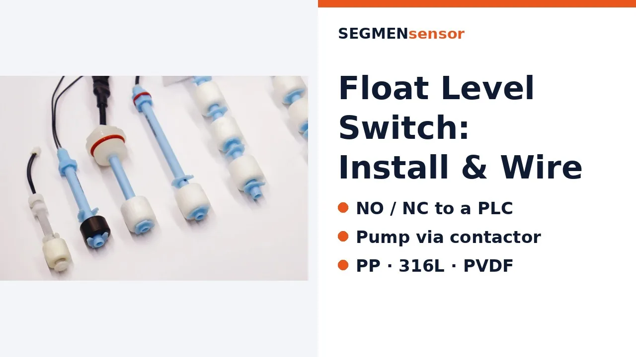
Use a float switch when the job is to act at fixed levels — start or stop a pump, raise a high or low alarm — with a simple dry contact and no power. Use a level transmitter when you need to know how full the tank is at every moment: it outputs a continuous 4–20 mA, 0–10 V or Modbus signal for a PLC, display or remote monitoring.
What is the difference between a float switch and a level transmitter?
A float switch answers a yes/no question — "is the liquid above this point?" — while a level transmitter answers "how high is the liquid?" as a number. The switch changes state at its setpoint; the transmitter's output moves smoothly from 0% to 100% of its range.
| Criterion | Float switch | Level transmitter |
|---|---|---|
| Output | Dry contact (SPDT: NO + NC), on/off | Continuous 4–20 mA, 0–10 V, RS485 Modbus or 4–20 mA + HART (by type) |
| What you learn | Liquid above or below 1–6 fixed points | Level value across the whole range, so trend, fill rate and volume |
| Power | None needed to switch | Loop or supply power, e.g. 12–36 V DC |
| Accuracy | ±5 mm actuation (±2 mm precision reed), independent of tank height | % of full scale, e.g. ±0.1% FS = ±5 mm on 0–5 mWC |
| Changing a setpoint | Move or re-order the switch point on the stem | Change it in the PLC or display — no work on the tank |
| Receiving device | Digital input, relay coil or contactor coil | Analog input, panel meter, controller or BMS/SCADA |
| Typical jobs | Pump on/off, overflow and dry-run protection, high/low alarms | Inventory, wells and reservoirs, batching, remote monitoring, PID control |
| Main limits | Moving float: liquid specific gravity ≥ 0.7, can stick with heavy build-up | Needs ranging and wiring; principle depends on the medium (density for hydrostatic, foam for ultrasonic) |
Float data are from the SEGMENsensor float level switch page; transmitter data from the submersible level transmitter and magnetostrictive level transmitter pages. The same point-versus-continuous logic applies to pressure, explained in pressure switch vs pressure transmitter.
When should I choose a float switch, and when a level transmitter?
Start from what the control system has to do with the signal, not from the sensor. If every action happens at a known height, a float switch is enough; if anyone needs the number, use a transmitter.
- Choose a float switch for sumps, pump pits, header tanks, coolant reservoirs and overflow or dry-run protection — anywhere the action is "start", "stop" or "alarm" at a fixed height.
- Choose a level transmitter for inventory and stock reporting, wells and reservoirs, batching by volume, remote monitoring, and any loop where the setpoint may change.
- Use both when an overflow or a dry-running pump would be costly: the transmitter runs the process, and a separate float switch wired to its own input or relay acts as the backstop.
Which is more accurate: a float switch or a level transmitter?
At its setpoint, a float switch is often as accurate as a transmitter on a short range and more accurate on a tall one, because its error is a fixed distance, not a percentage of full scale.
| Range of a ±0.1% FS transmitter | Transmitter error (calculated) | Float switch at a setpoint |
|---|---|---|
| 0–1 mWC | ±1 mm | ±5 mm (±2 mm precision reed) |
| 0–5 mWC | ±5 mm | ±5 mm (±2 mm precision reed) |
| 0–20 mWC | ±20 mm | ±5 mm (±2 mm precision reed) |
| 0–200 mWC | ±200 mm | Not practical: switch points are on the stem |
The transmitter tells you the level everywhere; the float switch only at its points. Where high resolution over the whole height matters, a magnetostrictive level transmitter reads the float position directly over 25–8000 mm, with repeatability of ±0.005 mm on the SGM-LS10 and SGM-LK10 (see how a magnetostrictive level transmitter works).
Worked example: replacing two float switches with one transmitter
A water tank is 5 m deep. Today a float switch stops the fill pump at 4.5 m and another raises a low alarm at 0.5 m. A 0–5 mWC submersible transmitter with 4–20 mA output could do both jobs in the PLC:
| Step | Formula | Result (calculated) |
|---|---|---|
| Pressure at the probe | P = ρ·g·h = 1,000 × 9.80665 × 4.5 | 44.13 kPa (4.5 mWC) |
| Current at 4.5 m (stop pump) | I = 4 + 16 × h ÷ 5 | 18.40 mA |
| Current at 0.5 m (low alarm) | I = 4 + 16 × 0.5 ÷ 5 | 5.60 mA |
| Transmitter accuracy | ±0.1% × 5,000 mm | ±5 mm — same as the float actuation accuracy |
The gain is a live level reading and setpoints that can be moved in software. The cost is a powered loop and the fact that one sensor now carries both functions — which is why a separate high-high float switch is commonly kept. Check other ranges with the 4–20 mA calculator and other liquids with the hydrostatic level calculator; 1 mWC = 9.80665 kPa follows from the standard acceleration of gravity listed in the NIST Guide to the SI, Appendix B.9 ↗.
How do the wiring and fail-safe behaviour differ?
A float switch is a contact; a transmitter is a powered signal source. That changes how each reports a fault.
- Float switch: connect the common to 24 V DC and the chosen contact to a PLC digital input. For alarms, use the normally closed contact so that a broken wire also raises the alarm. Do not switch a pump motor directly: let the float drive a relay or contactor coil (details in the float level switch selection guide).
- Transmitter: a 2-wire 4–20 mA loop carries power and signal on the same pair; 4 mA is the "live zero", so a broken wire reads 0 mA and is detectable. Many systems follow the NAMUR NE 43 recommendation and treat currents at or below 3.6 mA or at or above 21 mA as a sensor fault. Wiring types are compared in 2-wire vs 3-wire vs 4-wire transmitters.
- Safety functions: if a level alarm is part of a safety instrumented function, its design and independence are set by your hazard and risk analysis under IEC 61511-1 ↗, not by sensor choice alone.
SEGMENsensor float switches and level transmitters: key data
| Parameter | Float level switch | Submersible level transmitter |
|---|---|---|
| Measurement | Point: 1 point, or 2–6 points per stem | Continuous: 0–0.5 to 0–200 mWC, specified at order |
| Output | Reed switch SPDT, 10 A / 250 V AC (resistive) or 0.5 A / 100 V DC | 4–20 mA or 0–10 V |
| Accuracy | ±5 mm actuation; ±2 mm with precision reed | ±0.1% FS standard |
| Supply | None needed to switch | 12–36 V DC |
| Temperature | PP −20 to +85 °C; 316L −20 to +120 °C; high-temperature version +150 °C | −20 to +80 °C |
| Materials and protection | PP, 316L or PVDF float; IP68 | 316L probe, IP68; vented PVC cable 5 m standard |
| Process connection | 3/4" NPT standard | G1/2" standard |
| Samples | From 1 pc for qualification; volume per project | |
For non-contact measurement, SEU ultrasonic sensors cover 0.25–15 m at ±0.3% FS. Compare every principle in how to choose a liquid level sensor or browse all liquid level sensors.
Choosing between switches and transmitters for an OEM project?
Send the liquid, tank height, the actions you need (pump control, alarms, level reading) and the input your controller has. Our engineers will propose float switch points, a transmitter range, or both. Qualification samples 1–5 pcs in 5–7 working days · production 3–5 weeks · FOB China · reply within 24 hours.
Frequently Asked Questions
Yes, if the controller has an analog input: program the switch points as setpoints on the transmitter signal. Where an overflow or a dry-running pump would be costly, keep an independent float switch as the high-high or low-low alarm so one sensor failure cannot disable both control and protection.
No. A magnet in the float opens or closes a sealed reed contact, so the switch itself needs no supply. Power is only needed by the circuit it switches, such as 24 V DC to a PLC input or a relay coil.
No. A float switch only changes state at its switch points. A multi-point stem with 2–6 points gives level in steps; for a continuous reading use a level transmitter, such as a magnetostrictive transmitter that reads the float position over 25–8000 mm.
Usually a float switch: two switch points give pump start and stop, and a third can raise a high-level alarm. Drive the pump through a contactor, not through the float contact. Choose a transmitter when you also need the level reading or want to change start and stop levels without work in the pit.
Standard floats need a specific gravity of 0.7 or more, so very light liquids may not lift them. Heavy build-up, solids or sticky media can hold the float. For these, use a level transmitter suited to the medium, for example a non-contact ultrasonic sensor.