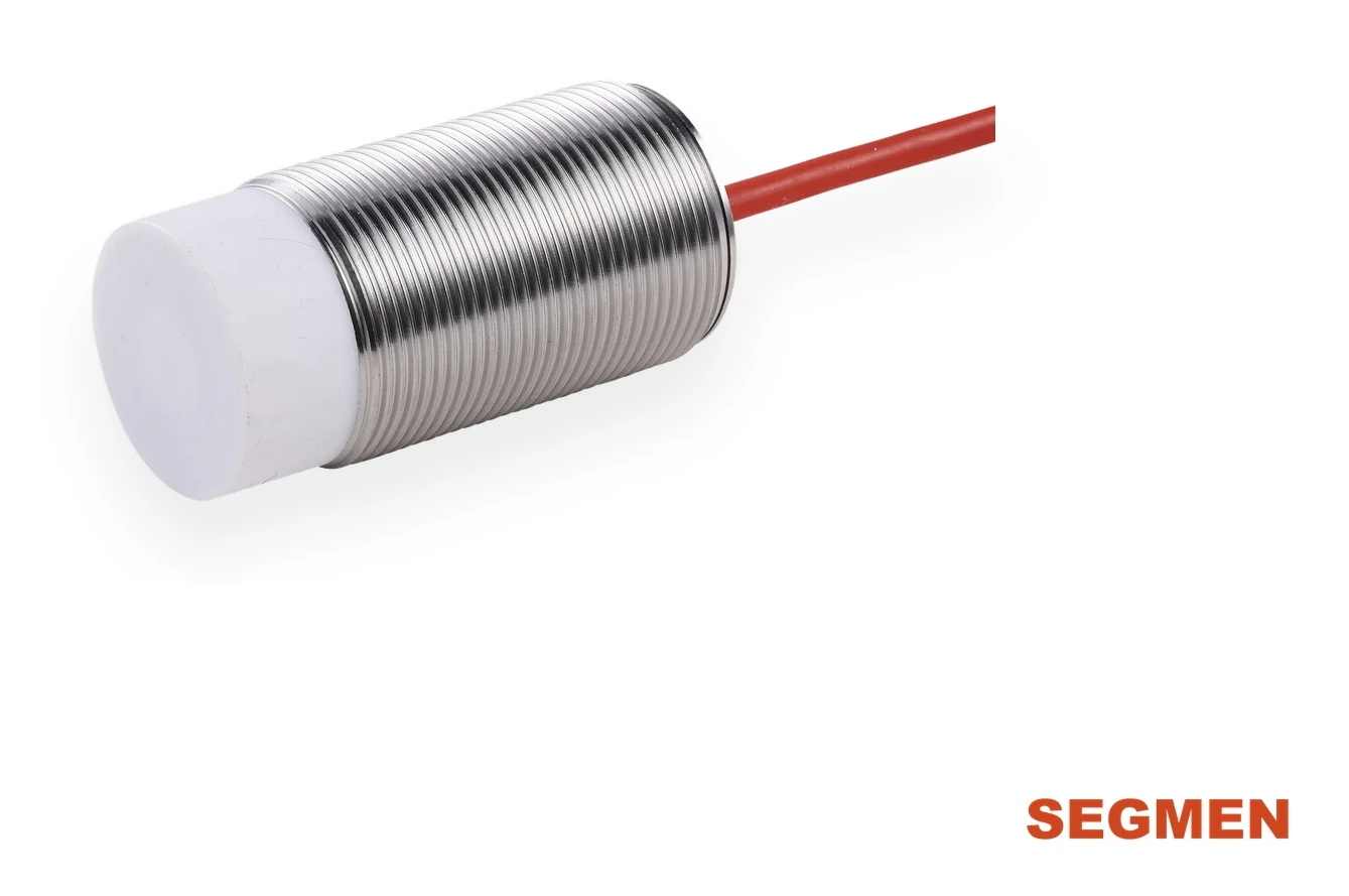
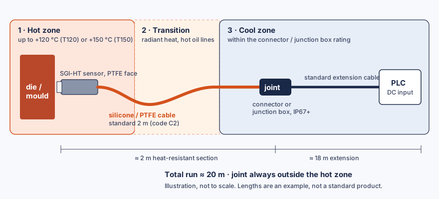
A 20 m run is normal for a proximity sensor; the length itself costs well under 1 V on a 24 V DC supply. What fails on hot machines is the joint. Keep the sensor and its silicone or PTFE cable in the hot zone, put the connector or junction box where the temperature is within its own rating, and run a standard extension cable from there to the PLC.
Can a high-temperature proximity sensor be supplied with a 20 m cable?
It can, in one of three builds. Every listed SGI-HT high-temperature inductive proximity sensor has a 2 m silicone or PTFE cable (code C2 in the part number). Longer cables and connector versions are not in the standard model list; they are evaluated per project and confirmed with the quotation. The table shows how the three builds compare.
| Build | Where the joint sits | Good for | Watch out for |
|---|---|---|---|
| Standard 2 m cable + junction box + extension | Outside the hot zone, about 2 m from the sensor | Most machines: the hot zone is small and a cool mounting point exists within 2 m | The box must be rated for its location (IP and temperature); route the 2 m section out of radiant heat |
| One continuous heat-resistant cable (e.g. 20 m) | At the PLC terminal or control cabinet | Hot zones longer than 2 m, or no place for a box near the machine | Project version, confirmed with the quotation; a spare sensor means replacing the whole cable run |
| Sensor with a connector + mating cable | At the sensor or on a short cable tail | Fast replacement without rewiring | The connector and its seal must be rated for the temperature where they sit; a connector inside the hot zone is the weakest point |
For a 20 m request the first build is usually the most robust choice: it keeps the heat-resistant section short and lets maintenance replace the sensor at the junction box. Material choice for the hot section is covered in PTFE vs silicone cable for high-temperature sensors.
Where should the connector go on a high-temperature sensor?
Outside the hot zone, at a point where the measured ambient temperature is inside the connector's own rating. The sensor's T120 or T150 rating covers the sensor and its cable, not a connector or terminal box added later.
- Measure the zones. Record the highest ambient temperature at the sensing face and along the first metres of cable, including radiant heat from dies, moulds or hot oil lines.
- Pick the sensor rating. Up to +120 °C choose T120; up to +150 °C choose T150 (M12, M18 or M30). Above +150 °C, see the SGC-HT high-temperature capacitive series.
- Find the first cool point. Mark where the ambient temperature drops inside the connector or junction box rating. If it is within 2 m, the standard C2 cable reaches it.
- Seal the joint. Use a connector or box with an IP rating at least equal to the sensor's IP67 (IP codes are defined in IEC 60529). Standard M12 circular connectors are specified in IEC 61076-2-101.
- Run the extension. From the joint, a standard PVC or PUR extension cable carries the signal the rest of the way to the PLC input card.
Does a 20 m cable affect a proximity sensor's signal?
Not the switching point. The sensing distance is set by the coil and oscillator in the sensor head, so cable length does not shorten it. Length only reduces the supply voltage that reaches the sensor and increases noise pick-up. The voltage drop is easy to check.
ΔV = I × 2 × L × ρ / A
I = current through the supply conductors (A), L = one-way cable length (m), ρ ≈ 0.0172 Ω·mm²/m for copper at 20 °C, A = conductor cross-section (mm²). The factor 2 counts the out and return conductors.
| Conductor size | Loop resistance, 20 m run | Drop at 100 mA | Drop at 200 mA |
|---|---|---|---|
| 0.14 mm² | 4.9 Ω | 0.49 V | 0.99 V |
| 0.25 mm² | 2.8 Ω | 0.28 V | 0.55 V |
| 0.34 mm² | 2.0 Ω | 0.20 V | 0.41 V |
| 0.50 mm² | 1.4 Ω | 0.14 V | 0.28 V |
All values are calculated at 20 °C as a worst case with the full current in both conductors; they are not measured values for a specific cable. The load current of each SGI-HT part number is given on the datasheet sent with the quotation.
Worked example: 20 m run on a 24 V and a 12 V supply
- A PNP SGI-HT sensor runs on 24 V DC through 20 m of 0.25 mm² conductors and switches a load drawing 100 mA. ΔV = 0.1 × 2 × 20 × 0.0172 / 0.25 ≈ 0.28 V. The sensor sees about 23.7 V, well inside 10–30 V DC.
- The same run on a 12 V supply with 0.14 mm² conductors and 200 mA leaves about 12 − 0.99 ≈ 11.0 V at the sensor. That is still above 10 V, but with only about 1 V of margin for supply tolerance.
- Heat adds little: only the 2 m hot section warms up. At +150 °C its resistance is about 1 + 0.00393 × 130 ≈ 1.5 times the 20 °C value, which adds only about 0.01 V on this run at 100 mA with 0.25 mm² conductors (calculated).
- Conclusion: on long runs use a 24 V DC supply and keep the load current within the datasheet value; cable length then has no practical effect on switching.
DC 2-wire versions (10–60 V DC) need one extra check: the cable drop adds to the sensor's own residual voltage, so confirm the residual voltage and off-state leakage current against your PLC input. Wiring for each output type is shown in NPN vs PNP proximity sensor wiring.
How do you route a long sensor cable near heat and power cables?
- Clamp the heat-resistant section along the machine frame, away from sharp edges, moving parts and direct flame or spatter.
- Leave a drip loop before the junction box so oil or condensate does not run into the joint.
- Run the extension in its own duct or tray, separated from motor, heater and drive output cables; cross power cables at right angles.
- Label both ends of the extension and the junction box with the sensor position, so a replacement goes back to the right input.
What goes wrong with long cables on hot sensors?
| Symptom | Likely cause | Fix |
|---|---|---|
| Signal drops out when the machine is hot, returns when it cools | Connector or terminal box inside the hot zone; seal or contacts overheat | Move the joint to the first cool point; use the 2 m C2 cable or a longer heat-resistant section |
| Output flickers when motors or heaters switch | Extension runs in the same duct as power or drive cables | Separate the sensor cable; cross power cables at 90° |
| Sensor works at 24 V but not on a 12 V system | Little voltage margin after cable drop at high load current | Use 24 V DC, a larger conductor or a lower load current |
| 2-wire sensor never switches the PLC input off | Off-state leakage current higher than the input accepts | Check leakage against the input card, or use a 3-wire NPN/PNP version |
| Cable jacket hardens or cracks near the machine | Cable route hotter than the cable material is meant for | Re-route out of radiant heat; choose PTFE or silicone by the install conditions |
If the sensor itself does not switch, start with why a proximity sensor is not detecting. For rating and housing choice in hot zones, see the high-temperature proximity sensor selection guide.
What should you send to order an SGI-HT sensor with a long cable or connector?
- Part number from the model finder, or housing (M8–M30), flush or non-flush mounting and output (NPN, PNP or DC 2-wire, NO or NC).
- Highest ambient temperature at the sensing face and along the cable route.
- Total cable length, the length that runs through the hot zone, and silicone or PTFE.
- Connector type if needed, and where on the cable it should sit.
- Supply voltage and PLC input type.
Need an SGI-HT sensor with a long cable or a connector?
Send the cable route temperatures, total length and connector type. Our engineers confirm the build. Qualification samples of 1–5 pcs in 5–7 working days · production lead time and MOQ confirmed with the quotation · FOB China · 100% T/T in advance · reply within 24 hours.
Frequently Asked Questions
The standard SGI-HT cable is 2 m of silicone or PTFE (code C2). A longer continuous cable is evaluated per project and confirmed with the quotation. On most machines the more robust build is the 2 m sensor cable joined outside the hot zone to a standard extension cable.
Connector versions are not in the standard SGI-HT model list; they are evaluated per project. Whatever the connector type, it must sit where the temperature is within the connector's own rating, so on hot machines it usually goes at the end of the heat-resistant cable, outside the hot zone.
No. The sensing distance is set by the coil and oscillator in the sensor head. A long cable only lowers the supply voltage at the sensor and picks up more electrical noise, so check the voltage drop and route the cable away from power cables.
Small conductors are usually enough. Over 20 m, 0.25 mm² copper drops about 0.28 V at 100 mA and 0.14 mm² about 0.99 V at 200 mA (calculated). On a 24 V DC supply both leave ample margin above the 10 V minimum; check the load current on the datasheet.
Yes. DC 2-wire SGI-HT versions run on 10–60 V DC. Add the cable drop to the sensor's residual voltage and compare the off-state leakage current with your PLC input; both values are on the datasheet sent with the quotation.
Qualification samples of 1–5 pcs ship in 5–7 working days once the build is confirmed. Production lead time and MOQ are confirmed with the quotation. Terms are FOB China with 100% T/T in advance, and we reply within 24 hours.