FREQUENCY-SWEEP LEVEL SWITCH

SGL-FS10 Frequency-Sweep Level Switch for Liquids, Solids and Slurries

SGL-FS10 is a point level switch that recognises the medium at its PEEK probe by dielectric constant (DK) using frequency-sweep measurement, so foam, build-up, flow and suspended solids do not cause false alarms. It detects media with DK ≥ 1.5, responds in 0.2 s, runs on 12–30 VDC and switches NPN or PNP, with a PWM mode that tracks changes in the medium.

DK ≥ 1.50.2 s responseIP67 · 10 MPaOEM volume supply
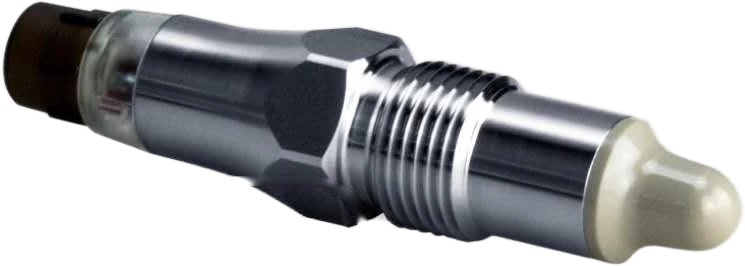
SEGMENsensor SGL-FS10 frequency-sweep level switch with PEEK probe, G1/2 thread and M12 connector

SGL-FS10: PEEK probe, G1/2 thread, M12 connector
Key facts

SEGMENsensor SGL-FS10 is a frequency-sweep point level switch for liquids, solids and slurries. It identifies the medium at the probe by its dielectric constant, ignores foam and build-up, and is used for high / low level alarms, interface detection and pump dry-run protection.

Last updated · SEGMENsensor Engineering Team

What is a frequency-sweep level switch?

A frequency-sweep level switch sends a signal across a range of frequencies through its probe and analyses how the signal strength changes. Each medium has its own dielectric constant (DK), so the sensor can tell whether the probe is in air, in the target medium, in foam or only covered by a thin film of build-up. That is why it keeps switching correctly where a simple capacitive switch would give a false alarm.

SGL-FS10 switches when the measured value (PV, 0–1000) reaches the alarm point AL1. The factory presets AL1 by medium class — 250 for low-DK media, 550 for water-based media and 720 for conductive slurries — and it can be set for your medium with the order.

Updated 2026-11-12 · Values from the SGL-FS10 datasheet, Rev 2026-11.

Specifications

SGL-FS10 Specifications

All values from the SGL-FS10 datasheet. Download the datasheet (PDF, 5 pages, no registration) — specifications, operating conditions, ordering code and dimensions.

ParameterValue
Measuring principleFrequency sweep
Hysteresis±1 mm
MediumDK ≥ 1.5
Response time0.2 s
Damping0–5 s (adjustable)
Repeatability±1 mm
Process temperature (standard)−40 to 115 °C
Process pressure (standard)−0.1 to 10 MPa
Other connectionsSee operating conditions
Mounting positionTop, bottom, side
Wetted partsPEEK; 304 or 316L stainless steel
Wetted surface roughnessRa < 0.8 µm
HousingStainless steel
Ingress protectionIP67
Humidity< 98 % RH, condensing
Ambient temperatureCable −25 to 70 °C; M12 −40 to 85 °C
Storage temperatureCable −25 to 70 °C; M12 −40 to 85 °C
Connection4 × 0.5 mm² cable / M12 4-pin connector
Voltage12–30 VDC
Start-up time< 1 s
Current (no load)8 mA typ., 40 mA max.
Reverse polarity protectionYes
Dielectric strength500 VAC
Output typeNPN / PNP / relay (external module)
Output logicNO / NC
Voltage drop (typ.)1.5 ± 0.5 V (Rload = 10 kΩ)
Output current20 mA max.
Leakage current< 100 µA
Short-circuit protectionYes
Damping0 s
Alarm point AL1Low-DK media 250; water-based 550; conductive slurry 720; alarm when PV ≥ AL1
Process value PV0–1000; calibrated to 100 in air and 900 in tap water
Alarm hysteresis25
Parameter lockParameters cannot be changed until unlocked

Operating conditions by mounting version

Process connectionIDContinuous temperature (ambient < 50 °C)Continuous pressureMax. temperature, 1 h (ambient < 50 °C)Max. pressure, 1 h
G1/2 thread, standard0−40 to 115 °C−0.1 to 10 MPa135 °C−0.1 to 10 MPa
G1/2 thread, reverse1−40 to 115 °C−0.1 to 10 MPa135 °C−0.1 to 10 MPa
G1/2 thread, heat sink2−40 to 150 °C−0.1 to 10 MPa—−0.1 to 10 MPa

Factory alarm points (AL1)

The alarm switches when the process value PV reaches AL1. PV range 0–1000, factory-calibrated to about 100 in air and about 900 in tap water; alarm hysteresis 25.

MediumFactory AL1Note
Low-DK media250Alarm when process value PV ≥ AL1
Water-based media550Default alarm point (order code D)
Conductive slurry720Can be set for your medium (order code C)
Selection

When to Choose SGL-FS10

If your application…Then
runs continuously up to 115 °Cchoose standard (ID 0) or reverse mounting (ID 1)
runs continuously up to 150 °Cchoose the heat-sink version (ID 2)
needs only a high / low alarmchoose software mode 0 (single), 1 (dual NO + NC) or 2 (dual NO + NO)
must follow a changing medium or separate several mediachoose PWM, software mode 4
handles a sticky conductive slurryspecify the alarm point (order code C), factory reference value 720
needs a continuous level reading in mmchoose the SGL-RF10 RF admittance level sensor or a magnetostrictive level transmitter instead
Features

SGL-FS10 Features and Typical Applications

Typical applications:

Principle

How SGL-FS10 Tells Media Apart

In PWM mode (software mode 4) the sensor outputs the medium’s DK value as a duty cycle. Different media in the same line or tank — products, water, cleaning fluid — can be told apart for continuous monitoring and product changeover. On a dairy line, for example, water is often used to separate two products in a pipe; the PWM signal shows exactly when the water-mixed section passes, so only that section is drained.

When two media have similar DK values, two switch points alone may not separate them. SGL-FS10 analyses how the signal strength changes across the sweep, so it switches on the target medium and stays off on the other.

Duty cycle 0%HLDuty cycle 25%HLDuty cycle 50%HLDuty cycle 75%HLDuty cycle 100%HL
PWM output duty cycle (illustration)
Switch point 100%0 Signal Sweep range
Medium A: switched (illustration)
Switch point 100%0 Signal Sweep range
Medium B: not switched (illustration)
Dimensions & Installation

SGL-FS10 Dimensions and Installation

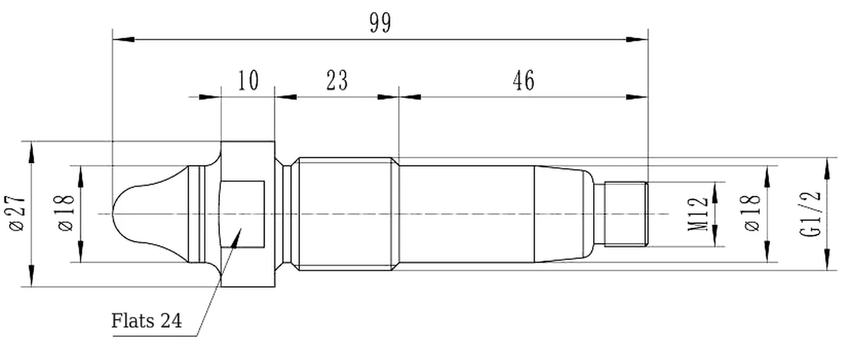
SGL-FS10 standard mounting (ID 0) dimension drawing, mm
Standard mounting (ID 0)
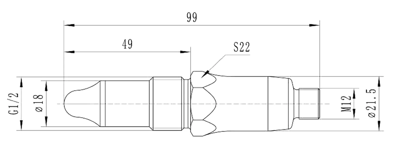
SGL-FS10 reverse mounting (ID 1) dimension drawing, mm
Reverse mounting (ID 1)
DimensionValue (mm)
Overall length99
Probe diameterØ18
Process threadG1/2
Hex (ID 0)S22
Body diameter (ID 0)Ø21.5
Shoulder / flats (ID 1)Ø27 / 24 A/F
Electrical connectionM12

Dimensions are for selection reference; the factory drawing applies. Other sizes and process connections on request.

1234
① High level (tank wall, side-mounted) · ② Low level (tank wall, side-mounted) · ③ Dry-run protection (vertical outlet pipe, side-mounted) · ④ Dry-run protection (horizontal pipe, top-mounted)
  1. Choose the position: top or upper side for a high-level alarm (1), lower side for a low-level alarm (2), or the outlet pipe before a pump for dry-run protection — side-mounted on a vertical pipe (3) or top-mounted on a horizontal pipe (4).
  2. Fit the sensor in the G1/2 port and tighten it with a torque wrench at the chosen measuring point.
  3. Connect 12–30 VDC and the NPN or PNP output; the alarm point is preset for water unless you ordered a specified value.
  4. Check the switching with the medium present and absent before putting the vessel into service.
Ordering

How to Order SGL-FS10

Build the ordering code from the fields below. Example: SGL-FS10-P-0D-6LNM-G0 = PNP output, single alarm, default alarm point (water), 316L, no seal, M12 connector, G1/2 standard probe.

FieldCodeDescription
ProductSGL-FS10Frequency-sweep smart level switch
OutputN / P / RNPN / PNP / relay (external module)
Software mode0 / 1 / 2 / 4Single alarm / dual alarm (NO + NC) / dual alarm (NO + NO) / PWM
Alarm pointD / CDefault (water) / customer-specified
Wetted material04 / 6L304 stainless / 316L stainless
SealN / CNo seal / specified seal material
ElectricalM / WM12 A-coded 4-pin / 4-core cable 1 m
Process connectionG0 / SG1/2 thread with standard probe / custom size

What to include in your RFQ

ItemPlease specify
MediumName, or dielectric constant if known; foam, build-up or solids present?
FunctionHigh / low alarm, interface detection, dry-run protection or PWM monitoring
ProcessTemperature and pressure, tank or pipe, mounting position
ElectricalNPN / PNP / relay module; NO / NC; M12 connector or cable
QuantitySamples and annual volume
1–5 pcsQualification samples
5–7 working daysSample lead time
Per quotationProduction lead time and MOQ
24 h replyEvery RFQ answered by an engineer
FAQ

SGL-FS10 — Frequently Asked Questions

What is a frequency-sweep level switch?
It is a point level switch that sweeps a signal across a frequency range and analyses the response, so it can tell the target medium apart from air, foam or a thin film of build-up by dielectric constant. SGL-FS10 uses this to switch reliably where simple capacitive switches give false alarms.
Which media can SGL-FS10 detect?
Liquids, solids and slurries with a dielectric constant (DK) of 1.5 or higher. Alarm points are preset by medium class — 250 for low-DK media, 550 for water-based media and 720 for conductive slurries — and can be specified with the order.
Will foam or build-up cause false alarms?
No. The frequency sweep tells foam and build-up apart from the real medium, and a foam layer can be set to be ignored. For sticky conductive slurries, order a specified alarm point (code C) based on the 720 reference value.
Which mounting version should I choose?
Up to 115 °C continuous process temperature choose standard mounting (ID 0) or reverse mounting (ID 1); up to 150 °C choose the heat-sink version (ID 2). All three use a G1/2 thread and withstand −0.1 to 10 MPa.
Do I need to register to download the datasheet?
No. The SGL-FS10 datasheet PDF downloads directly from this page with specifications, operating conditions, ordering code and dimension drawings. For a selection review or a quotation, send your medium and process data to our engineers.

Need SGL-FS10 for Your Project?

Send the medium, function, process temperature and output — an engineer replies within 24 hours on working days with a quotation and the datasheet.

Request a Quote for SGL-FS10

Tell us your specification — our engineers reply within 24 hours.

OEM volume supply · samples in 5–7 days · info@segmensensor.com

Related Products

Related Level Sensors

info@segmensensor.com